
iPad Pro 11" 1st Gen Screen Replacement

Introdução
Ir para o passo 1Follow this guide to replace the screen on your iPad Pro 11" 1st gen.
If your battery is swollen, take appropriate precautions.
The LiDAR sensor assembly attached to the screen is paired with the Face ID hardware. You'll need to transfer it to your new screen to keep Face ID functionality.
O que você precisa
Fix Kit
Este kit contém todas as peças e ferramentas necessárias para executar este guia.

Peças


Ferramentas


Exibir mais…
-
-
Camera module, ambient light sensors, proximity senor, and front microphone
-
Display cables
-
Screen magnets
-
LCD edges
Do the screen magnets and the adhesive come with the replacement screen?
-
-
-
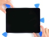
Apply a heated iOpener to the right edge of the screen for two minutes.
-
-
Ferramenta utilizada neste passo:Clampy - Anti-Clamp$24.95
-
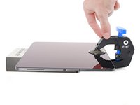
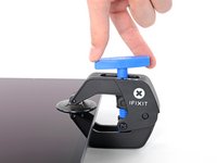
Pull the blue handle backwards to unlock the Anti-Clamp's arms.
-
Place an object under your iPad so it rests level between the suction cups.
-
Position the suction cups near the middle of the right edge—one on the top, and one on the bottom.
-
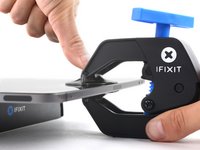
Hold the bottom of the Anti-Clamp steady and firmly press down on the top cup to apply suction.
-
-
-
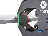
Wait one minute to give the adhesive a chance to release and present an opening gap.
-
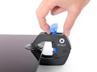
If your screen isn't getting hot enough, you can use a hair dryer to heat along the right edge of the iPad.
-
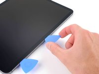
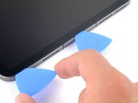
Insert an opening pick under the screen when the Anti-Clamp creates a large enough gap.
-
Skip the next step.
-
-
-
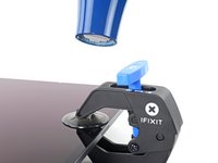
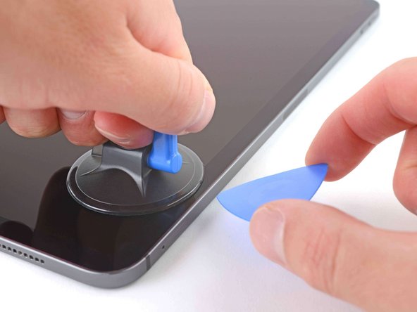
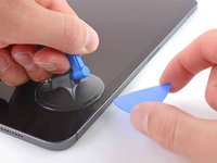
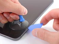
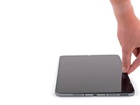
Apply a suction handle to the right edge of the screen, about 5 cm from the bottom edge.
-
Pull up on the suction handle with firm, constant pressure to create a gap large enough to insert an opening pick.
-
Insert the tip of an opening pick into the gap.
-
-
-
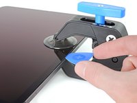
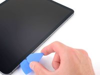
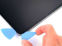
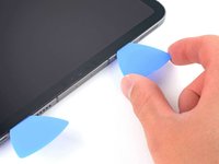
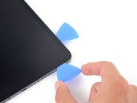
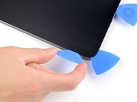
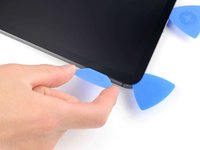
Insert a new opening pick in the gap you just created.
-
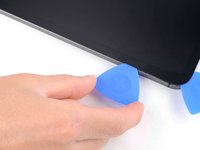
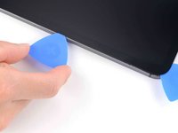
Slide the pick along the right edge to separate the adhesive.
-
Leave the pick in the top right corner to prevent the adhesive from re-sealing.
-
-
-
Apply a heated iOpener to the top edge of the screen for two minutes.
-
-
-
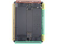
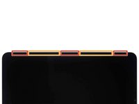
Don't insert an opening pick more than 2 mm near the top left and right edges or you'll damage the ambient light sensors.
-
Don't insert an opening pick more than 1 mm near the middle of the top edge or you'll damage the camera module, proximity sensor, and front microphone.
I thought the orange and red squares in this image represented where the listed components (the ambient light sensors, the camera module, proximity sensor, and front mic) are located. And if that’s the case, shouldn’t the warning be to separate the adhesive outside of the marked locations to help minimize the chance of damaging those components? I’m wondering why you would focus your prying efforts on the areas where there are really delicate and easily damaged parts…
I noticed the same thing, and ended up needing to guess to limit insertion to 1mm and 2mm respectively, or avoid those areas.
-
-
-
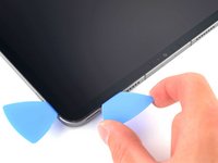
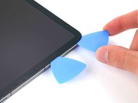
Insert a new opening pick in the gap you just created.
-
Slide the pick along the top right edge, stopping when you reach the right ambient light sensor.
-
Leave the pick to the right of the sensor to prevent the adhesive from re-sealing.
-
-
-
Apply a heated iOpener to the bottom edge of the screen for two minutes.
-
-
-
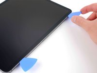
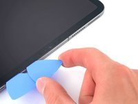
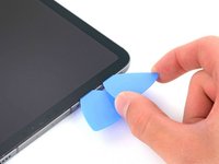
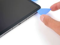
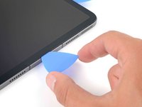
Insert a new opening pick in the bottom right corner below the existing pick.
-
Slide the pick around the bottom right corner to separate the adhesive.
-
-
-
-
Apply a heated iOpener to the left edge of the screen for two minutes.
-
-
-
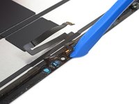
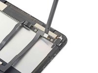
The display cables are located within small indents of the frame and require an opening pick to be inserted at a 45° angle.
-
There are flat sections of the frame which require an opening pick to be inserted horizontally.
-
-
-
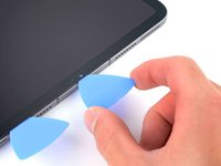
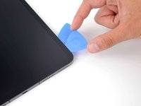
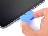
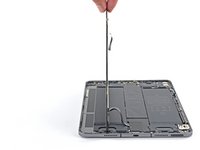
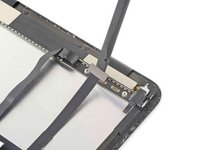
Insert an opening pick at a 45˚ angle just above the bottom left corner.
-
Carefully slide the pick along the left edge, stopping when you reach the flat section of the frame.
-
-
-
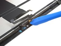
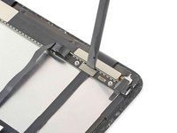
Separate the remaining adhesive, making sure to follow the instructions exactly as written.
-
Slide the pick at a 45˚ downward angle and don't insert the pick more than 5 mm.
-
Slide the pick horizontally and don't insert the pick more than 5 mm.
-
-
-
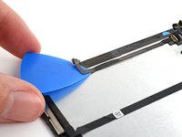
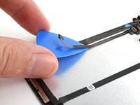
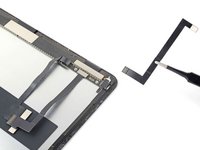
Grab two opposing corners of the screen and gently separate the rest of the adhesive.
-
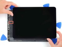
Shift the screen towards the bottom right corner of the frame until the ambient light sensor ribbon cable near the top edge is uncovered.
-
-
Ferramenta utilizada neste passo:FixMat$36.95
-
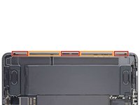
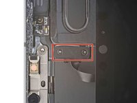
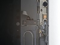
Use a Phillips screwdriver to remove the two screws securing the ambient light sensor cable bracket to the logic board:
-
One 1.3 mm screw
-
One 2.0 mm screw
-
-
Ferramenta utilizada neste passo:Tweezers$4.99
-
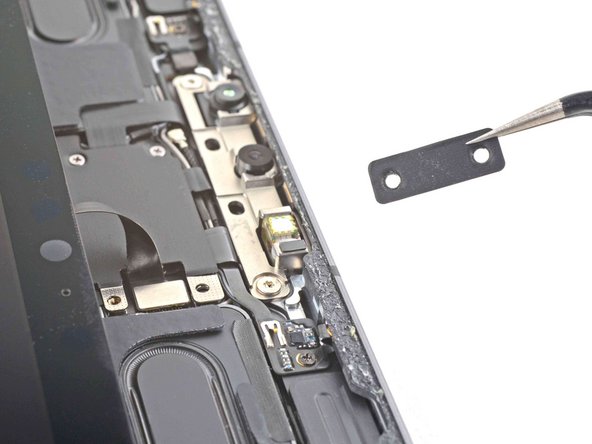
Use tweezers or your fingers to remove the bracket.
-
-
-
Use the flat end of a spudger to disconnect the ambient light sensor cable by lifting straight up on the press connector.
-
-
-
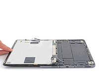
Grip the right edge of the screen and fold it open like a book.
-
Lay the screen down over the left edge of the iPad.
-
-
-
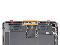
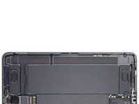
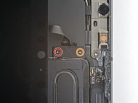
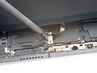
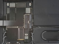
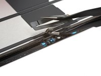
Use a Phillips screwdriver to remove the three 1.2 mm screws securing the bottom cable shield to the logic board.
This seems out of order.
Not really, 1st step release top ambient light cable , open iPad and remove the 3 screws
-
-
-
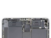
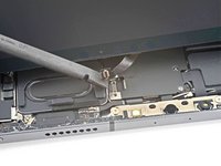
Use tweezers or your fingers to remove the bottom cable shield.
-
-
-
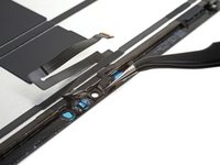
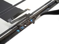
Use a Phillips screwdriver to remove the 1.8 mm screw securing the battery connector to the logic board.
There's a section missing here about inserting the playing cards to remove the connection to the battery. You can see these in the next screen nut it's not mentioned. Other users have reported shorts and damage due to missing this step. I'm not an expert but I noticed this and wanted to mention it.
After removing the screw, slip a thin piece of plastic or playing card stock or a thin guitar pic under the mother board on the edge closest to the battery to separate the contact. THIS IS NOT A PRY-UP DISCONNECT, THE STAINLESS COVER IS PART OF THE MOTHERBOARD.
-
-
-
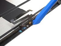
Use the pointed end of a spudger to pry up and disconnect the top two display cables.
-
-
-
Disconnect the two remaining display cables.
-
-
-
The LiDAR sensor assembly is composed of four total sensors:
-
Two ambient light sensors
-
One proximity sensor
-
One microphone
I broke off the right most ambient light sensor. How much trouble am I in?
-
-
-
Heat an iOpener and apply it to the top of the screen for two minutes.
-
-
Ferramenta utilizada neste passo:Tweezers$3.99
-
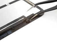
Insert one arm of your angled tweezers between the ambient light sensor and the screen.
-
Pry up to separate the sensor from the screen.
-
Repeat this procedure for the other ambient light sensor.
The ambient light sensor system is constructed with a few component parts arranged in layers starting with its connection cable down to the last part that is attached to the glass.
It is not super clear from the photos/instructions between which layers we need to pry to separate the sensor from the part that touches the glass. I'd like to see a straight on view of the exposed layer.
I think I ended up separating the ambient light sensors incorrectly; my exposed sensor layers don't look the same as those you see of the stock part for sale on this site. Those have that layer with the small circle, but the instruction photos here show that layer left attached to the glass.
My FaceID doesn't work and I suspect it may be because of this mistake I made.
Yes, the diffuser was a black film layer with a white milky circle.
We broke one of the sensors off from the cable, and ended up just having one working ambient light sensor.
FaceID however continued to work with that one sensor in the end.
quak -
Following the guide instructions left the diffuser layer of the ambient light sensor adhered to the screen. The use of an Exacto knife with a straight 6mm perpendicular blade, was used to separate this layer from the screen. All of the other sensors were separated successfully with the use of the Exacto knife.
Thank you for that hint! A carefully applied Exacto knife worked much better than the original recommendation, for all of the sensors!
quak -
-
-
-
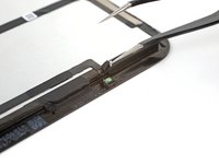
Insert one arm of your angled tweezers between the proximity sensor cable and the screen.
-
Slide the tweezers toward the screen while prying to separate the sensor from the screen.
-
-
-
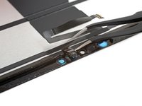
Peel off any tape covering the microphone.
-
-
-
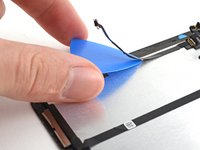
Slide an opening tool under the microphone to separate its adhesive.
-
Pry up to separate the microphone from the screen.
-
-
-
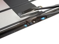
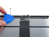
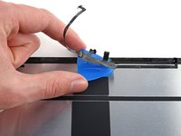
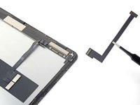
Slide an opening pick under the LiDAR sensor assembly cable to separate it from the screen.
-
-
Ferramenta utilizada neste passo:Tesa 61395 Tape$5.99
-
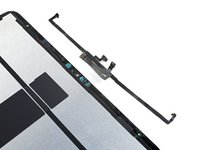
Align the LiDAR sensor assembly on your replacement screen.
-
Use Tesa tape, or similar double-sided tape, to secure the cables to the screen.
-
Use E6000 adhesive, or similar adhesive, to secure the sensors to their cutouts on the screen.
-
-
-
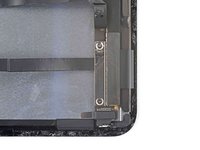
The display cable connectors are located under a bracket near the bottom right corner of the screen.
-
-
-
Slide an opening pick under the non-removable display cable to loosen it from the bracket.
-
-
-
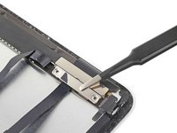
Use a Phillips screwdriver to remove the two 1.2 mm screws securing the display cable bracket.
-
-
-
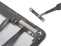
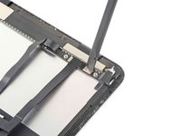
Use the flat end of a spudger to pry up and disconnect the narrow display cable.
-
Remove the narrow display cable. Set it aside for reassembly.
-


To reassemble your device, follow these instructions in reverse order.
Take your e-waste to an R2 or e-Stewards certified recycler.
Repair didn’t go as planned? Try some basic troubleshooting, or ask our Answers community for help.
To reassemble your device, follow these instructions in reverse order.
Take your e-waste to an R2 or e-Stewards certified recycler.
Repair didn’t go as planned? Try some basic troubleshooting, or ask our Answers community for help.
Cancelar: não concluí este guia.
17 outras pessoas executaram este guia.

Equipe

2Comentários do guia
Don't forgot to remove side magnets from old screen and to transfert them to your new screen.
What size Tesa tape is needed in step 42?