Ir para o conteúdo principal

Hot Tools HPK12 Control Assembly Replacement

O que você precisa

  1. Hot Tools HPK12 Control Assembly Replacement, Prerequisite Only: passo 1, imagem 1 %32 Hot Tools HPK12 Control Assembly Replacement, Prerequisite Only: passo 1, imagem 2 %32 Hot Tools HPK12 Control Assembly Replacement, Prerequisite Only: passo 1, imagem 3 %32
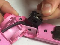
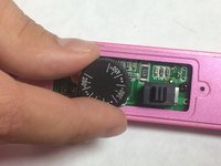
    • Remove round plastic cover near cord base by prying under the side with the metal spudger.

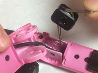
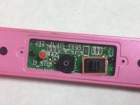
    • Flip the device and remove the other round plastic cover near the base of the cord.

    • Use the Phillips #1 screwdriver to remove the 5.5mm PH1 screw and washer under the plastic cover and set both aside.

  2. Hot Tools HPK12 Control Assembly Replacement: passo 2, imagem 1 %32
    • Use the metal spudger to push the center pin through to the other side.

  3. Hot Tools HPK12 Control Assembly Replacement: passo 3, imagem 1 %32 Hot Tools HPK12 Control Assembly Replacement: passo 3, imagem 2 %32
    • Lift back plastic cover to expose spring assembly.

    • Be careful not to damage the power cord by bending or twisting it too much while performing this step.

    • Grip the exposed end of the spring assembly and remove it.

    • The side with the two ends of the spring goes into the recessed area of the iron

  4. Hot Tools HPK12 Control Assembly Replacement: passo 4, imagem 1 %32
    • Use the JIS #0 screwdriver to remove the two 3.5mm “J0” screws that attach the control assembly cover to the flat iron base.

  5. Hot Tools HPK12 Control Assembly Replacement: passo 5, imagem 1 %32 Hot Tools HPK12 Control Assembly Replacement: passo 5, imagem 2 %32 Hot Tools HPK12 Control Assembly Replacement: passo 5, imagem 3 %32
    • Lift upward on the control assembly cover to remove it from the flat iron base.

    • Remove dial and switch cover and set aside.

  6. Hot Tools HPK12 Control Assembly Replacement: passo 6, imagem 1 %32 Hot Tools HPK12 Control Assembly Replacement: passo 6, imagem 2 %32 Hot Tools HPK12 Control Assembly Replacement: passo 6, imagem 3 %32
    • Use your JIS #0 screw driver to remove the two 6mm “J0” screws that are attached to the flat iron base and set them aside.

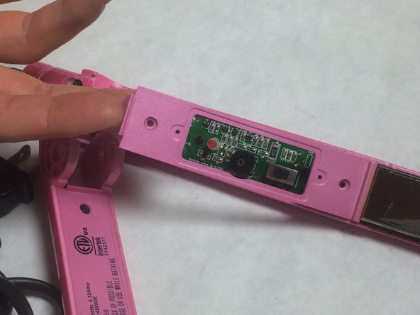
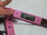
    • Lift the backing plate upwards to remove it from the flat iron.

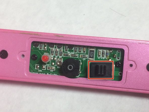
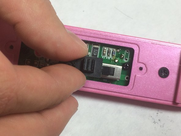
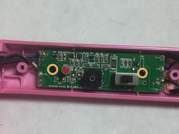
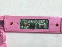
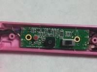
    • Use the Phillips #0 screwdriver to remove two 4mm “PH0” screws that attach the circuit assembly to the flat iron base.

Conclusão

To reassemble your device, follow these instructions in reverse order.

Uma outra pessoa concluiu este guia.

Aaron Whitlock

Membro desde: 10/24/16

249 Reputação

Autoria de 2 guias

Equipe

IUPUI, Team 3-4, Baechle Fall 2016 Membro de IUPUI, Team 3-4, Baechle Fall 2016

IUPUI-BAECHLE-F16S3G4

Membros da 4

Autoria de 5 guias

0 comentários

Adicione um comentário

Exibir estatísticas:

Últimas 24 horas: 2

Últimos 7 dias: 7

Últimos 30 dias: 17

Duração total: 2,644