Ir para o conteúdo principal

Esta versão pode conter edições incorretas. Mude para o último instantâneo verificado.

O que você precisa

  1. , Remoção dos parafusos pentalobe: passo 1, imagem 1 %32
    • Antes de proceder, descarregue o seu iPhone para abaixo de 25%. Uma bateria de íons de lítio carregada pode pegar fogo e/ou explodir, se perfurada acidentalmente.

    • Desligue o seu iPhone antes de começar a desmontagem.

    • Remova os dois parafusos pentalobe de 3,9 mm de ambos os lados do conector Lightning.

  2. , Colocar fita adesiva sobre todas as rachaduras: passo 2, imagem 1 %32 , Colocar fita adesiva sobre todas as rachaduras: passo 2, imagem 2 %32 , Colocar fita adesiva sobre todas as rachaduras: passo 2, imagem 3 %32
    • Se o vidro de seu visor estiver rachado, mantenha as rachaduras sob controle e evite danos corporais durante o reparo cobrindo o vidro com fita adesiva.

    • Coloque tiras sobrepostas de fita adesiva transparente sobre a tela do iPhone até que toda a superfície fique coberta.

    • Isso manterá os estilhaços de vidro sob controle e garantirá a integridade estrutural enquanto o display é liberado e elevado.

    • Use óculos de segurança para proteger seus olhos de qualquer vidro que possa ser liberado durante o reparo.

  3. , Prevenção da separação do visor: passo 3, imagem 1 %32 , Prevenção da separação do visor: passo 3, imagem 2 %32 , Prevenção da separação do visor: passo 3, imagem 3 %32
    • Nos próximos passos você vai estar puxando a tela para fora do corpo do fone. O visor (display) é composto por uma tela de vidro e uma moldura de plástico com clipes metálicos.

    • Independente da ferramenta que você use, você precisa puxar para cima com segurança o visor inteiro.

    • Se o vidro começar a se separar do plástico, como mostra a primeira figura, passe uma ferramenta de abertura de plástico por entre a moldura de plástico e o corpo metálico do fone para liberar os clipes metálicos da estrutura.

    • Se você estiver realizando a remontagem de um fone com uma moldura de visor separada, pode ser que você precise colocar uma tira fina de adesivo entre a moldura de plástico e o vidro, para manter fechado o fone.

  4. , Instruções com o Anti-Clamp: passo 4, imagem 1 %32 , Instruções com o Anti-Clamp: passo 4, imagem 2 %32 , Instruções com o Anti-Clamp: passo 4, imagem 3 %32
    • As próximas duas etapas demonstram o Anti-Clamp, uma ferramenta que projetamos para facilitar o procedimento de abertura. Se não estiver usando o Anti-Clamp, pule duas etapas para um método alternativo.

    • Para obter instruções completas sobre como usar o Anti-Clamp, consulte este guia.

    • Puxe a pega azul para trás para destravar os braços do Anti-Clamp.

    • Deslize os braços pela borda esquerda ou direita do seu iPhone.

    • Posicione as ventosas próximo à borda inferior do iPhone, diretamente acima do botão home - uma pela dianteira e a outra pela traseira.

    • Aperte as ventosas uma contra a outra para aplicar sucção na área desejada.

    • Se a superfície do seu iPhone é muito escorregadia para o Anti-Clamp se prender, você pode usar o pedaço de fita incluído para deixar a superfície mais aderente.

  5. : passo 5, imagem 1 %32 : passo 5, imagem 2 %32 : passo 5, imagem 3 %32
    • Puxe a pega azul para a frente para travar os braços.

    • Gire a pega 360 graus no sentido horário até que as ventosas comecem a se esticar.

    • Certifique-se de que as ventosas permaneçam alinhadas uma com a outra. Se elas começarem a ficar desalinhadas, solte um pouco as ventosas e realinhe os braços.

    • Insira uma palheta de abertura sob a tela quando o Anti-Clamp tiver formado um vão grande o suficiente.

    • Se o Anti-Clamp não formar espaço suficiente, gire a pega um quarto de volta.

    • Não gire a pega mais do que um quarto de volta de cada vez e espere alguns segundos entre cada volta. Deixe que o Anti-Clamp e o tempo façam o trabalho por você.

    • Pule as próximas duas etapas.

  6. , Procedimento de abertura manual: passo 6, imagem 1 %32
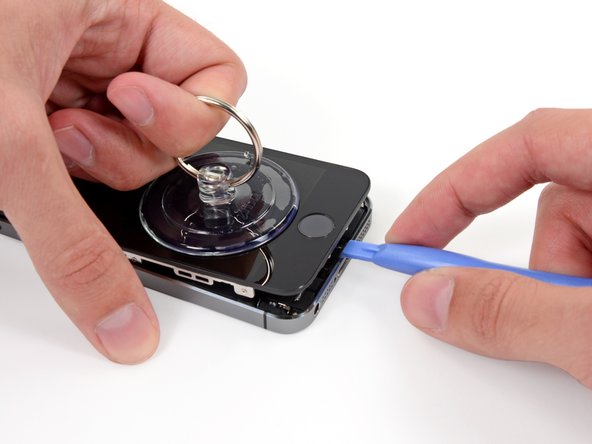
    • Se você não tiver um Anti-Clamp, use uma ventosa de sucção simples para erguer o painel dianteiro:

    • Pressione uma ventosa de sucção sobre a tela, imediatamente acima do botão home.

    • Certifique-se de que a ventosa está completamente pegada na tela para obter uma vedação apertada.

  7. , Começar a erguer o conjunto do painel dianteiro: passo 7, imagem 1 %32
    • O painel dianteiro está preciso com clipes e há vários cabos planos conectando-o ao resto do fone. O seu objetivo é desprender os clipes e abrir o fone somente o bastante para desconectar os cabos. Vá devagar e com cuidado para evitar danos.

    • Certifique-se de que a ventosa de sucção esteja fixada firmemente ao ao conjunto do painel dianteiro, próximo ao botão home.

    • Enquanto segura o iPhone com uma mão, puxe para cima pela ventosa de sucção para separar ligeiramente a extremidade com o botão home do painel dianteiro da estrutura traseira.

    • Com uma ferramenta de abertura de plástico, comece a fazer alavanca para baixo nas bordas da estrutura traseira, afastando-as do conjunto do painel dianteiro, enquanto puxa para cima com a ventosa de sucção.

    • Use o tempo que for necessário e empregue força firme e constantemente. O conjunto do painel dianteiro tem um ajuste muito mais apertado do que na maioria dos outros dispositivos.

  8. : passo 8, imagem 1 %32 : passo 8, imagem 2 %32
    • Não tente remover completamente o conjunto do painel dianteiro da estrutura traseira, pois há vários cabos planos sensíveis conectando-os.

    • Puxe na lingueta de plástico para liberar o vácuo da ventosa de sucção.

    • Remova a ventosa de sucção da tela.

  9. , Remoção do suporte do cabo da identificação por toque: passo 9, imagem 1 %32 , Remoção do suporte do cabo da identificação por toque: passo 9, imagem 2 %32 , Remoção do suporte do cabo da identificação por toque: passo 9, imagem 3 %32
    • Abra o fone apenas o bastante para revelar o suporte metálico que cobre o cabo do botão home.

    • Não abra demais o fone ou você estará arriscando danos ao cabo do botão home ou ao soquete no qual este é plugado. Mantenha o cabo frouxo - se ele estiver distendido, foi demais.

    • Somente o conjunto do botão home original poderá permitir o uso da funcionalidade da identificação por toque. Se você romper o cabo, a instalação de um novo botão home apenas restaurará as funções normais do botão home, mas não os recursos de identificação por toque.

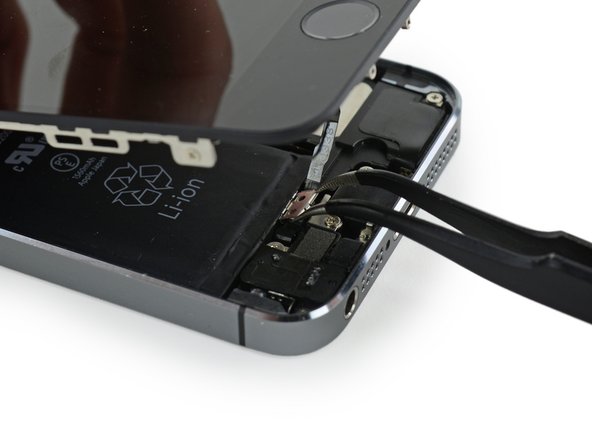
    • Com a ponta pontiaguda de uma espátula, empurre o suporte, liberando-o e remova-o com uma pinça.

    • Os dois próximos passos referem-se à remontagem. Pule eles e vá para o passo 12 até a remontagem.

  10. : passo 10, imagem 1 %32 : passo 10, imagem 2 %32
    • Durante a remontagem você precisará reinstalar o suporte do cabo da identificação por toque. A parte superior do suporte precisa deslizar entre a bateria e o conector do cabo da identificação por toque, na frente da lingueta metálica. O botão tem que engatar para baixo no conector.

    • Deslize a parte superior do suporte sobre o conector do cabo da identificação por toque da esquerda para a direita.

  11. : passo 11, imagem 1 %32 : passo 11, imagem 2 %32
    • Durante a remontagem, use a ponta plana de uma espátula para engatar para baixo a parte dianteira do suporte do cabo da identificação por toque sobre o conector do cabo.

    • Se o suporte não engatar para baixo diretamente, pode ser que você precise remover e deslizar o suporte no conector do cabo novamente, para um melhor ajuste.

  12. , Desconectar o conector do cabo do botão home: passo 12, imagem 1 %32 , Desconectar o conector do cabo do botão home: passo 12, imagem 2 %32
    • Use a ponta pontiaguda de uma espátula para fazer alavanca e separar o conector do cabo do botão home de seu soquete.

    • Certifique-se de que você está separando o conector do cabo de seu soquete e não fazendo alavanca no soquete inteiro. O soquete está sobre o seu próprio cabo, que está colado, e que pode ser destacado se você não tiver cuidado.

  13. , Abrir o fone: passo 13, imagem 1 %32 , Abrir o fone: passo 13, imagem 2 %32 , Abrir o fone: passo 13, imagem 3 %32
    • Uma vez solto o conector, puxe a ponta com o botão home do conjunto, afastando-o da estrutura traseira, usando a parte superior do fone como uma dobradiça.

    • Abra o visor a um ângulo de 90º e apoie-o em algo para deixá-lo de pé enquanto você executa os trabalhos no fone.

    • Engate uma fita de borracha para manter o visor no lugar com segurança enquanto executa os trabalhos. Isso evita que os cabos do visor sejam submetidos a uma tensão imprópria.

    • Se estiver com pressa, use uma lata de bebida fechada para apoiar o visor.

  14. : passo 14, imagem 1 %32
    • Remova os dois parafusos PH000 de 1,6 mm que fixam o suporte metálico do conector da bateria à placa lógica.

  15. : passo 15, imagem 1 %32
    • Remova o suporte metálico do conector da bateria do iPhone.

  16. : passo 16, imagem 1 %32 : passo 16, imagem 2 %32
    • Com a ponta plana de uma espátula, erga com cuidado o conector da bateria de seu soquete na placa lógica.

    • Tenha muito cuidado para erguer somente o conector da bateria e não o soquete na placa lógica. Se você fizer alavanca no soquete da placa lógica ou na placa inteira, pode ser que você destrua o soquete ou danifique componentes adjacentes na placa.

  17. : passo 17, imagem 1 %32
    • Remova os seguintes parafusos que fixam o suporte de cabos do conjunto do painel dianteiro na placa lógica.

    • um parafuso Phillips PH000 de 1,7 mm

    • um parafuso Phillips PH000 de 1,2 mm

    • um parafuso Phillips PH000 de 1,3 mm

    • mais um parafuso Phillips PH000 de 1,7 mm

    • Este parafuso de 1,7 mm não costuma ser atraído por uma chave magnetizada. Tome cuidado para não perdê-lo durante a remoção.

    • É especialmente importante para a remontagem rastrear os seus parafusos neste passo. O uso acidental do parafuso de 1,3 mm ou de um dos parafusos de 1,7 mm no furo direito inferior resultará em um danos significativos na placa lógica, fazendo com que o fone não inicialize mais corretamente.

    • Tenha cuidado para não apertar demais os parafusos e não exerça força neles. Se os parafusos não rosquearem com facilidade no aparafusamento, é provável que eles não tenham o tamanho certo.

  18. : passo 18, imagem 1 %32
    • Remova o suporte de cabos do conjunto do painel dianteiro da placa lógica.

  19. : passo 19, imagem 1 %32 : passo 19, imagem 2 %32
    • Com uma espátula ou uma unha, desconecte o cabo da câmera frontal e dos sensores.

  20. : passo 20, imagem 1 %32 : passo 20, imagem 2 %32
    • Certifique-se de que a bateria esteja desconectada antes de desconectar ou reconectar os cabos neste passo.

    • Desconecte o conector do cabo da tela LCD.

    • Na remontagem de seu fone, pode ser que o cabo da tela LCD escape do conector. Isso pode resultar em linhas brancas ou tela preta quando você ligar novamente o seu fone. Se isso acontecer, simplesmente conecte novamente o cabo e faça power cycle no seu fone. A melhor forma de fazer power cycle no seu fone é desconectar e reconectar a bateria.

  21. : passo 21, imagem 1 %32 : passo 21, imagem 2 %32
    • Finalmente, desconecte o conector do cabo do digitalizador.

  22. : passo 22, imagem 1 %32
    • Remova o conjunto do painel dianteiro da estrutura traseira.

  23. Este passo não foi traduzido. Ajude a traduzi-lo

    : passo 23, imagem 1 %32 : passo 23, imagem 2 %32
    • Insert a SIM card eject tool or a paperclip into the small hole in the SIM card tray.

    • Press to eject the tray. This may require a significant amount of force.

  24. Este passo não foi traduzido. Ajude a traduzi-lo

    : passo 24, imagem 1 %32
    • Remove the SIM Card tray assembly from the iPhone.

    • When reinserting the SIM card, ensure that it is in the proper orientation relative to the tray.

  25. Este passo não foi traduzido. Ajude a traduzi-lo

    : passo 25, imagem 1 %32 : passo 25, imagem 2 %32
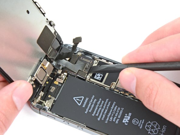
    • Use a spudger to gently pry the button assembly cable up from its socket on the logic board.

    • Be very careful to only pry up on the connector and not the socket on the logic board. If you pry up on the logic board socket, you may break the connector entirely.

  26. Este passo não foi traduzido. Ajude a traduzi-lo

    : passo 26, imagem 1 %32 : passo 26, imagem 2 %32 : passo 26, imagem 3 %32
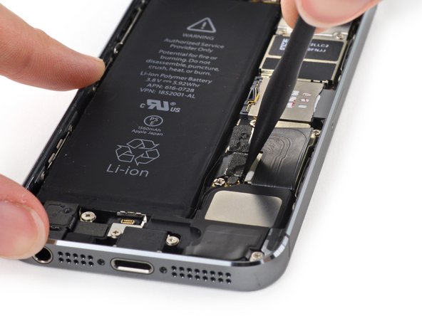
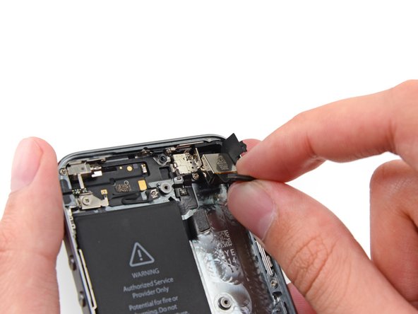
    • Use a spudger to pry the Lightning connector cable up from its socket on the logic board.

    • Fold the Lightning connector cable out of the way of the logic board.

  27. Este passo não foi traduzido. Ajude a traduzi-lo

    : passo 27, imagem 1 %32 : passo 27, imagem 2 %32
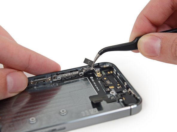
    • Use the tip of a spudger to pry the antenna cable up from its socket on the logic board.

  28. Este passo não foi traduzido. Ajude a traduzi-lo

    : passo 28, imagem 1 %32 : passo 28, imagem 2 %32
    • Use the flat end of a spudger to disconnect the rear-facing camera cable from its socket on the logic board.

  29. Este passo não foi traduzido. Ajude a traduzi-lo

    : passo 29, imagem 1 %32
    • Remove any tape covering the camera flash bracket.

  30. Este passo não foi traduzido. Ajude a traduzi-lo

    : passo 30, imagem 1 %32
    Ferramenta utilizada nesse passo:
    Standoff Screwdriver for iPhones
    $5.49
    Comprar
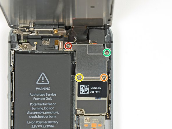
    • Remove the following screws from the logic board:

    • One 2.4 mm Phillips #000 screw

    • This screw also holds a small metal contact beneath the logic board. It's held in place underneath a plastic bracket, but if you see it slipping out, refer to this step to remove it.

    • Two 2.3 mm Phillips #000 screws

    • Four 2.8 mm standoff screws

    • Standoff screws are best removed using a standoff screwdriver or bit.

    • In a pinch, a small flathead screwdriver will do the job—but use extra caution to ensure it doesn't slip and damage surrounding components.

  31. Este passo não foi traduzido. Ajude a traduzi-lo

    : passo 31, imagem 1 %32 : passo 31, imagem 2 %32
    • Use a plastic opening tool to lift the logic board up enough to grab with your fingers.

  32. Este passo não foi traduzido. Ajude a traduzi-lo

    : passo 32, imagem 1 %32 : passo 32, imagem 2 %32 : passo 32, imagem 3 %32
    • Pull the logic board slightly away from the rear facing camera.

    • Do not try to remove the logic board just yet, as it is still connected by an antenna cable on the back.

    • Flip the logic board toward the battery, as if you are turning the page in a book.

  33. Este passo não foi traduzido. Ajude a traduzi-lo

    : passo 33, imagem 1 %32 : passo 33, imagem 2 %32
    • Use the flat end of a spudger to disconnect the antenna cable on the back of the logic board.

    • Remove the logic board from the iPhone.

  34. Este passo não foi traduzido. Ajude a traduzi-lo

    : passo 34, imagem 1 %32 : passo 34, imagem 2 %32 : passo 34, imagem 3 %32
    • At this point, a small metal plate near the rear facing camera is loose and may come free from its recess.

    • Because it is very small and easy to lose, it's best to remove this plate and set it aside while you continue to work on your phone.

    • Use tweezers to remove the plate from beneath the bracket to the left of the rear-facing camera.

    • When reassembling, orient the plate with the small tab to the right and the longest flat edge against the top of the phone.

  35. Este passo não foi traduzido. Ajude a traduzi-lo

    : passo 35, imagem 1 %32 : passo 35, imagem 2 %32 : passo 35, imagem 3 %32
    • Using a pair of tweezers, flip the rubber camera cover out of its clip and toward the outside of the rear case.

    • Do not attempt to fully remove this cover. It is attached to the rear case and only needs to be flipped open, not removed.

  36. Este passo não foi traduzido. Ajude a traduzi-lo

    : passo 36, imagem 1 %32 : passo 36, imagem 2 %32 : passo 36, imagem 3 %32
    • Remove the rear-facing camera from the rear case.

    • During reassembly, the camera cable should bend in a 'U' shape to slot in behind the logic board.

    • If the rubber camera bumper has shifted, be sure to replace it before reassembling your iPhone.

  37. Este passo não foi traduzido. Ajude a traduzi-lo

    : passo 37, imagem 1 %32
    • Remove the two 1.6 mm Phillips #000 screws securing the rear-facing camera bracket.

  38. Este passo não foi traduzido. Ajude a traduzi-lo

    : passo 38, imagem 1 %32
    • Remove the rear-facing camera bracket from the rear case.

  39. Este passo não foi traduzido. Ajude a traduzi-lo

    : passo 39, imagem 1 %32
    • Remove the rubber camera bumper from the case.

  40. Este passo não foi traduzido. Ajude a traduzi-lo

    : passo 40, imagem 1 %32 : passo 40, imagem 2 %32 : passo 40, imagem 3 %32
    • Insert the tip of a spudger into the hole in the battery adhesive tab near the headphone jack.

    • Lift the tab up slightly and use the spudger to unfold the tab from its recess.

  41. Este passo não foi traduzido. Ajude a traduzi-lo

    : passo 41, imagem 1 %32 : passo 41, imagem 2 %32 : passo 41, imagem 3 %32
    • Pull the battery adhesive tab straight up from the phone.

    • Cut the black battery adhesive tab between the two white adhesive strips, separating them.

  42. Este passo não foi traduzido. Ajude a traduzi-lo

    : passo 42, imagem 1 %32 : passo 42, imagem 2 %32
    • Try to keep the strips flat and unwrinkled during this procedure; wrinkled strips will stick together and break instead of pulling out cleanly.

    • Slowly pull one of the battery adhesive strips away from the battery, toward the bottom of the iPhone.

    • Pull steadily, maintaining constant tension on the strip as it slips out from between the battery and the rear case. For best results, pull the strip at a 60º angle or less.

  43. Este passo não foi traduzido. Ajude a traduzi-lo

    : passo 43, imagem 1 %32 : passo 43, imagem 2 %32 : passo 43, imagem 3 %32
    • Guide the strip carefully around the corner and up the side of the battery.

    • Be careful not to snag it on the corner of the battery or on any of the other internal iPhone components.

    • The strip will stretch to many times its original length. Continue pulling, re-grabbing the strip near the battery if necessary, until the entire strip comes free.

  44. Este passo não foi traduzido. Ajude a traduzi-lo

    : passo 44, imagem 1 %32 : passo 44, imagem 2 %32 : passo 44, imagem 3 %32
    • Repeat to remove the second adhesive strip.

    • If you removed both strips successfully, skip the next two steps.

    • If either of the adhesive strips break underneath the battery and cannot be retrieved, try to remove the remaining strip, and then proceed to the next step.

  45. Este passo não foi traduzido. Ajude a traduzi-lo

    : passo 45, imagem 1 %32
    • If any of the adhesive strips broke off and the battery remains stuck to the rear case, prepare an iOpener or use a hair dryer to heat the rear case directly behind the battery.

  46. Este passo não foi traduzido. Ajude a traduzi-lo

    : passo 46, imagem 1 %32
    Ferramenta utilizada nesse passo:
    Plastic Cards
    $2.99
    Comprar
    • Flip the iPhone back over and insert a plastic card between the case side of the battery and the rear case.

    • Be careful to keep the card as flat as possible to avoid bending the battery, which may damage it and cause it to release dangerous chemicals.

    • Press the card in farther to break up the adhesive behind the battery.

  47. Este passo não foi traduzido. Ajude a traduzi-lo

    : passo 47, imagem 1 %32 : passo 47, imagem 2 %32
    • Remove the battery from the rear case.

    • When installing the battery, refer to this guide to replace your battery's adhesive strips.

  48. Este passo não foi traduzido. Ajude a traduzi-lo

    : passo 48, imagem 1 %32
    • Remove the following Phillips #000 screws from the vibrator bracket:

    • One 1.7 mm screw

    • One 2.5 mm screw

  49. Este passo não foi traduzido. Ajude a traduzi-lo

    : passo 49, imagem 1 %32
    • With a set of tweezers, remove the vibrator bracket.

  50. Este passo não foi traduzido. Ajude a traduzi-lo

    : passo 50, imagem 1 %32
    • Remove the 1.7 mm Phillips #000 screw securing the vibrator to the rear case.

  51. Este passo não foi traduzido. Ajude a traduzi-lo

    : passo 51, imagem 1 %32
    • Use a set of tweezers to remove the vibrator from the rear case.

  52. Este passo não foi traduzido. Ajude a traduzi-lo

    : passo 52, imagem 1 %32
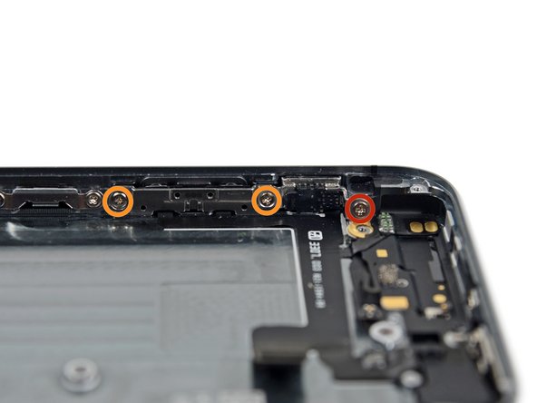
    • Remove the following screws securing the volume button and ringer switch brackets to the side of the rear case:

    • One 1.9 mm Phillips screw

    • Two 1.6 mm Phillips screws

  53. Este passo não foi traduzido. Ajude a traduzi-lo

    : passo 53, imagem 1 %32 : passo 53, imagem 2 %32 : passo 53, imagem 3 %32
    • Use the tip of a spudger to pry the ringer switch bracket from the side of the rear case.

    • Remove the ringer switch.

    • Note the orientation for reassembly: The red line should be at the top of the button. The notch in the back of the ringer switch button should be in the same position as, and mate with, the mechanical switch on the cable.

  54. Este passo não foi traduzido. Ajude a traduzi-lo

    : passo 54, imagem 1 %32 : passo 54, imagem 2 %32 : passo 54, imagem 3 %32
    • Use a spudger to pry the volume button bracket from the side of the rear case.

    • Remove the volume buttons.

    • During reassembly, make sure the '+' (volume up) button is in the hole closest to the ringer switch.

  55. Este passo não foi traduzido. Ajude a traduzi-lo

    : passo 55, imagem 1 %32 : passo 55, imagem 2 %32
    • Use tweezers to pull the rubber rear-facing camera cover out of its slot in the rear case.

  56. Este passo não foi traduzido. Ajude a traduzi-lo

    : passo 56, imagem 1 %32
    • Remove the 1.3 mm Phillips #000 screw securing the logic board antenna bracket to the rear case.

  57. Este passo não foi traduzido. Ajude a traduzi-lo

    : passo 57, imagem 1 %32
    • Remove the logic board antenna bracket.

  58. Este passo não foi traduzido. Ajude a traduzi-lo

    : passo 58, imagem 1 %32
    • Remove the 2.1 mm Phillips #000 screw securing the contact clip and power/sleep button bracket.

  59. Este passo não foi traduzido. Ajude a traduzi-lo

    : passo 59, imagem 1 %32 : passo 59, imagem 2 %32
    • Remove the contact clip from the iPhone.

    • During reassembly, be sure the bracket is properly seated between the rear-facing camera flash and the top edge of the case.

  60. Este passo não foi traduzido. Ajude a traduzi-lo

    : passo 60, imagem 1 %32 : passo 60, imagem 2 %32 : passo 60, imagem 3 %32
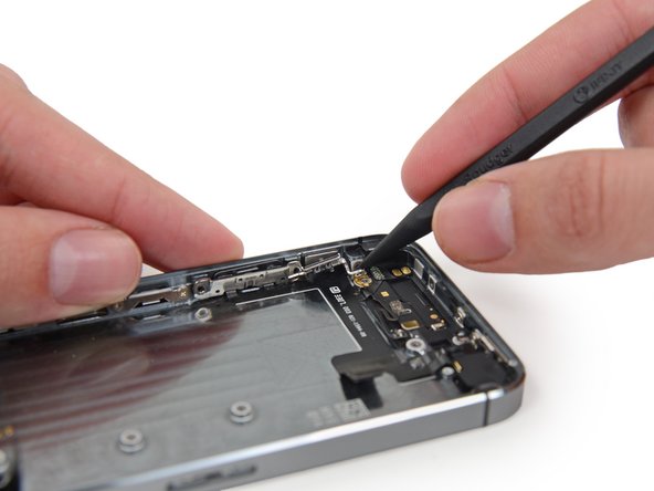
    • Slide the flat end of a spudger under the upper component assembly cable to free it from the rear case.

  61. Este passo não foi traduzido. Ajude a traduzi-lo

    : passo 61, imagem 1 %32 : passo 61, imagem 2 %32 : passo 61, imagem 3 %32
    • Run the flat end of the spudger under the portion of the cable near the volume control buttons.

  62. Este passo não foi traduzido. Ajude a traduzi-lo

    : passo 62, imagem 1 %32 : passo 62, imagem 2 %32 : passo 62, imagem 3 %32
    • Use the tip of a spudger to free the adhesive securing the vibrator contact portion of the upper assembly cable from the rear case.

    • If the flash assembly has not already popped out of its hole in the rear case, use the tip of a spudger to push it free.

  63. Este passo não foi traduzido. Ajude a traduzi-lo

    : passo 63, imagem 1 %32 : passo 63, imagem 2 %32 : passo 63, imagem 3 %32
    • Use the tip of a spudger to free the microphone portion of the assembly from the case.

  64. Este passo não foi traduzido. Ajude a traduzi-lo

    : passo 64, imagem 1 %32 : passo 64, imagem 2 %32
    • Use a set of tweezers to swing the power/sleep button bracket away from the case.

  65. Este passo não foi traduzido. Ajude a traduzi-lo

    : passo 65, imagem 1 %32 : passo 65, imagem 2 %32 : passo 65, imagem 3 %32
    • Use the tip of a spudger to push the power/sleep button into the phone slightly.

    • Use a set of tweezers to remove the button.

    • Double check the orientation of the button for reassembly. The two "L" shapes should be upside down, and the metal bar should be folded onto the top of the button.

  66. Este passo não foi traduzido. Ajude a traduzi-lo

    : passo 66, imagem 1 %32 : passo 66, imagem 2 %32
    • Unclip the power/sleep button bracket hinge from the post holding it in the iPhone.

  67. Este passo não foi traduzido. Ajude a traduzi-lo

    : passo 67, imagem 1 %32
    • Remove the upper component assembly from the iPhone.

    • This cable has many delicate ends and can tear very easily. If you encounter any resistance when you lift the cable, stop immediately. Run a spudger under the entire cable and try lifting again.

Linha de Chegada

83 outras pessoas executaram este guia.

Sam Goldheart

Membro desde: 10/18/12

465.777 Reputação

Autoria de 538 guias

Equipe

iFixit Membro de iFixit

Staff

Membros da 135

Autoria de 16.817 guias

7 comentários

Parts list calls for:

iPhone 5s Logic Board Grounding Bracket and Contact Clip

not sure why.

Instructions at link for these parts says they are "visible in steps 53 through 56 of the Upper Component Cable Replacement guide". Not quite right.

- Steps 56 & 57 show removal of the Logic Board Grounding Bracket, but instructions call it the “logic board antenna bracket”. Screw that goes through the logic board into this is marked in red on step 30.

- “Small metal contact beneath logic board” referred to in Step 30 goes under the Logic Board Grounding Bracket. See also Step 34.

- Step 59 shows removal of the Contact Clip.

Winston - Responder

Great guide. Be careful that the silence button is workable before reassembling everything. It is easy to think the switch is in place when it really isn’t. Also, be careful when adhering the new cable to the housing as accurate alignment is essential for the cable to not have a significant kink in it when trying to align it with the logic board. I found that following the markings on the back housing were pretty close when adhering the cable and deciding where to put it. I got sick of messing with battery adhesives and tried to use none and the battery is totally stable once the phone is reassembled and doesn’t rattle around at all.

tmzert - Responder

Quick question: Is this cable compatible with iPhone 5 SE A1723?

mithm_2009 - Responder

Brilliant. My only comments are that it doesn’t mention that the new replacement ribbon cable has adhesive strips that need to be used, so be very careful in the positioning of it before sticking it down. Also, the power button part of the new cable needs to be stuck unto the retaining bracket with glue which you need to have at hand. I used UHU as it is fairly inert and can be easily repositioned. Finally, I suggest you will probably need a magnifier of some kind (stand or glasses) to help in this repair as it is a lengthy process, and best taken slowly.

G C - Responder

Great guide! The steps were clear and detailed enough for me to replace upper component ribbon without messing anything else up (which, unfortunately, sometimes does happen) :) The only small thing that I would perhaps mention is that the rubber camera bumper also comes attached to the replacement ribbon, so you don’t have to worry about the old one when you’re removing it. Same with the small strip of adhesive that is holding the contact clip - I recommend removing it since the replacement ribbon also has the same adhesive strip already attached to it.

Sida - Responder

Adicione um comentário

Exibir estatísticas:

Últimas 24 horas: 5

Últimos 7 dias: 28

Últimos 30 dias: 133

Duração total: 79,724