Introdução
Follow this guide to replace a broken front panel assembly on an iPad Air 2 Wi-Fi. The front panel or display assembly consists of the glass digitizer on top and the fused LCD underneath. In the iPad Air 2, these two parts are not separable and must be replaced as one piece.
Note that the fingerprint scanner in the home button is paired to the iPad's logic board. In order to maintain Touch ID functionality, you must transfer your original home button to the new display assembly.
This process can fix issues like a cracked glass digitizer, a non-responsive touchscreen, or a broken LCD screen.
Be very careful when you isolate the battery using a battery blocker. The battery contacts are easily damaged, resulting in irreversible damage to the logic board.
O que você precisa
-
-
Heat the iOpener for thirty seconds.
-
Throughout the repair procedure, as the iOpener cools, reheat it in the microwave for an additional thirty seconds at a time.
-
-
-
Remove the iOpener from the microwave, holding it by one of the two flat ends to avoid the hot center.
-
-
-
Fill a pot or pan with enough water to fully submerge an iOpener.
-
Heat the water to a boil. Turn off the heat.
-
Place an iOpener into the hot water for 2-3 minutes. Make sure the iOpener is fully submerged in the water.
-
Use tongs to extract the heated iOpener from the hot water.
-
Thoroughly dry the iOpener with a towel.
-
Your iOpener is ready for use! If you need to reheat the iOpener, heat the water to a boil, turn off the heat, and place the iOpener in the water for 2-3 minutes.
-
-
-
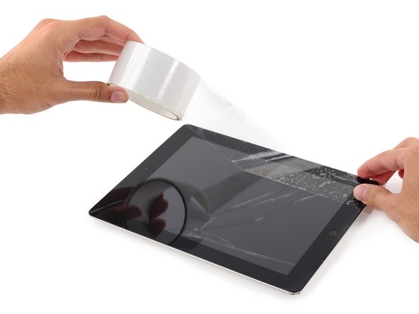
If your display glass is cracked, keep further breakage contained and prevent bodily harm during your repair by taping the glass.
-
Lay overlapping strips of clear packing tape over the iPad's display until the whole face is covered.
-
Do your best to follow the rest of the guide as described. However, once the glass is broken, it will likely continue to crack as you work, and you may need to use a metal prying tool to scoop the glass out.
-
-
-
Handling it by the tabs on either end, place a heated iOpener over the top edge of the iPad.
-
Let the iOpener sit on the iPad for two minutes to soften the adhesive securing the front panel to the rest of the iPad.
-
-
-
As you follow the directions, take special care to avoid prying in the following areas:
-
Home Button
-
Front Facing Camera
-
Main Camera
-
-
Ferramenta utilizada neste passo:Clampy - Anti-Clamp$24.95
-
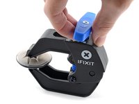
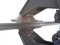
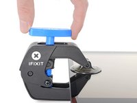
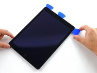
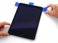
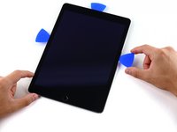
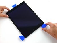
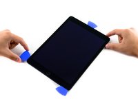
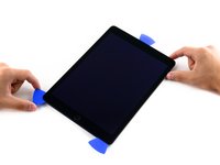
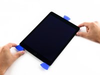
Elevate the iPad enough for the Anti-Clamp's arms to rest above and below the screen.
-
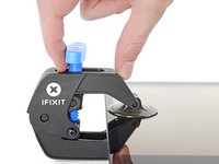
Pull the blue handle towards the hinge to disengage opening mode.
-
Position the suction cups near the top edge of the iPad—one on the front, and one on the back.
-
Push down on the cups to apply suction to the desired area.
-
-
-
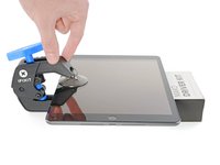
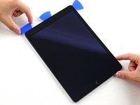
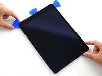
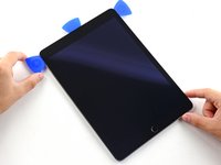
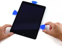
Push the blue handle away from the hinge to engage opening mode.
-
Turn the handle clockwise until you see the cups start to stretch.
-
Wait one minute to give the adhesive a chance to release and present an opening gap.
-
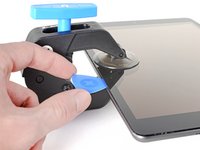
Insert an opening pick under the screen when the Anti-Clamp creates a large enough gap.
-
Skip the next two steps.
-
-
-
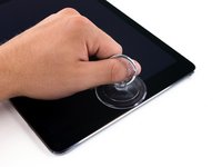
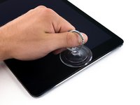
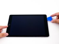
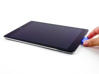
Place a suction cup over the iPad's front-facing camera and press down to create a seal.
-
-
-
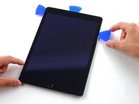
Firmly pull up on the suction cup to create a small gap between the front panel and the rear case.
-
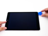
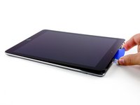
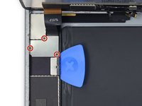
Once you've opened a sufficient gap, insert an opening pick into the gap to prevent the adhesive from resealing.
-
-
-
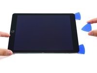
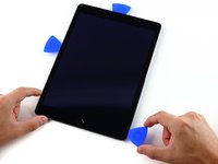
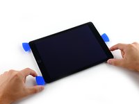
Slide the pick along the edge of the display, towards the headphone jack.
-
If there is still a considerable amount of resistance when sliding the opening pick, repeat the iOpener heating procedure and apply additional heat.
-
-
-
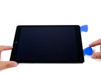
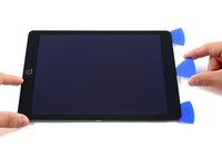
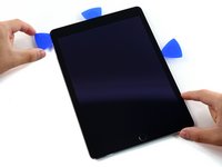
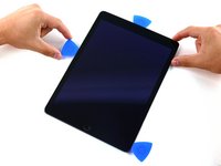
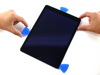
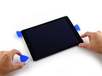
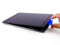
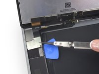
Slide the second pick along the top edge of the iPad, towards the Sleep/Wake Button.
-
-
-
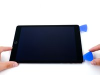
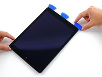
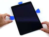
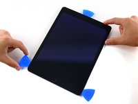
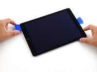
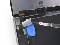
Bring the right opening pick down and around the top right corner of the iPad.
-
-
-
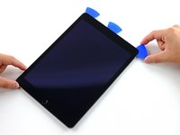
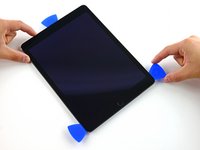
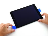
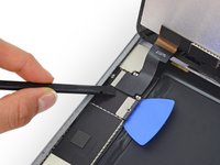
Bring the left opening pick around the top left corner of the tablet.
-
-
-
-
Reheat the iOpener and lay it over the right edge of the display to loosen the adhesive underneath.
-
-
-
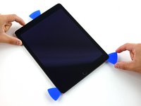
Slide the left-hand opening pick about halfway down the edge of the display.
-
-
-
Slide the opposite opening pick down to the bottom right corner of the iPad.
-
-
-
Slide the left-hand opening pick down the edge of the display until you reach the corner.
-
-
-
Bring the right-hand opening pick around the bottom corner of the iPad.
-
-
-
Slide the left-hand opening pick along the bottom edge of the display, then remove it from the bottom right corner of the iPad.
-
-
-
Twist the remaining pick by the front-facing camera to separate the top edge of the display assembly from the rear case.
-
-
-
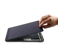
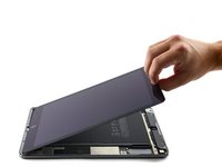
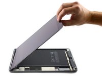
Continue lifting the display assembly from the front-facing camera side.
-
Pull the display slightly away from the bottom edge to completely separate it from the rear case.
-
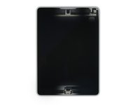
Keep lifting until the display assembly is roughly perpendicular to the body of the iPad.
-
-
-
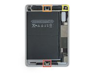
Remove the single 1.8 mm Phillips screw securing the battery terminals to their contacts on the logic board.
-
-
-
Slide a battery isolation pick underneath the battery connector area of the logic board, and leave it in place while you work.
-
Alternatively, make a battery blocker using a playing card and slide it underneath the logic board connector to disconnect the battery.
-
-
-
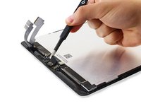
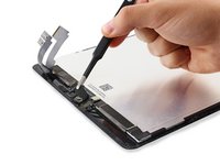
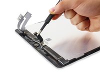
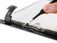
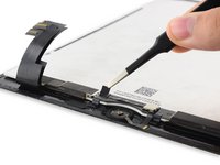
Remove the three 1.3mm Phillips screws from the display cable bracket.
-
Remove the bracket.
-
-
-
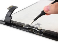
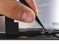
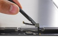
Disconnect the display data connector from its socket on the logic board.
-
-
-
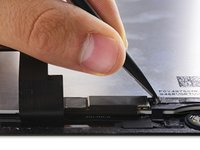
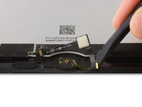
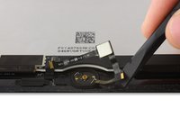
Disconnect the two remaining digitizer cables underneath the display data cable.
-
-
-
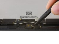
Use a plastic opening tool to pry the bracket off the back of the Home Button.
-
-
Ferramenta utilizada neste passo:Tesa 61395 Tape$8.95
-
Remove the Home Button bracket and peel up the tape connected to it.
-
Scrape off as much of the old adhesive residue from the bracket as you can, then clean it with acetone or high-concentration (90% or greater) isopropyl alcohol.
-
Secure the bracket with hot-melt glue, superglue, or high-strength double-sided tape. Make sure the bracket is aligned correctly before allowing your adhesive to cure, or the home button will not click when pressed.
-
-
-
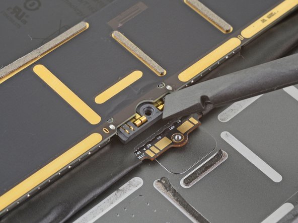
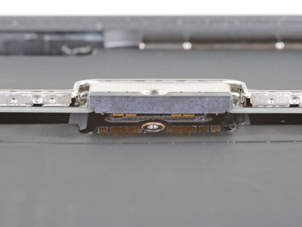
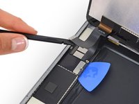
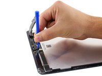
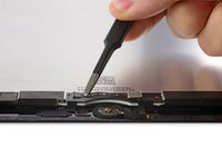
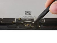
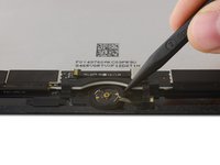
Use the flat end of a spudger to flip up the retaining flap on the Home Button cable socket.
-
-
-
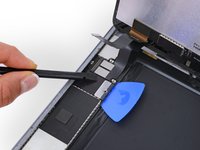
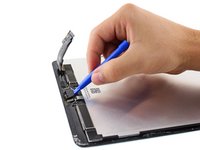
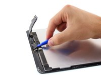
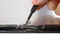
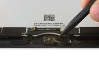
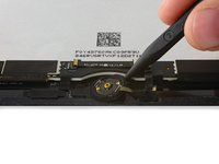
Use the flat end of a spudger to peel up the Home Button ribbon cable and Touch ID control chip.
-
-
-
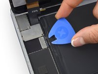
Reheat your iOpener and lay it over the bottom edge of the display to loosen the adhesive on the Home Button gasket.
-
-
-
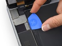
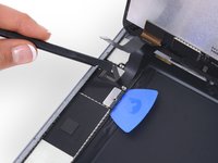
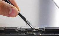
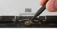
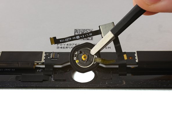
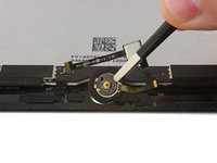
Use the pointed end of a spudger to gently pry the Home Button assembly up from the display.
-
-
-
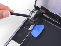
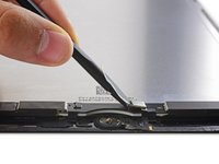
Continue working the tip of the spudger around the edge of the gasket until the gasket is fully separated from the front panel.
-
-
-
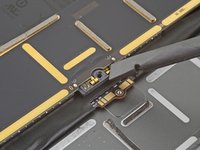
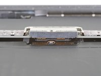
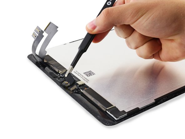
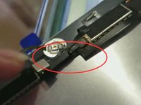
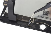
Examine your replacement part, and your original display carefully to be sure they match.
-
Your replacement screen may be missing the sleep/wake sensor that is necessary for Smart Cover use. If you want to maintain functionality you will need to transfer the component.
-
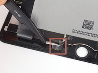
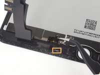
Desolder the four solder pads from the lower left of the display to remove the sensor assembly cable.
-


To reassemble your device, follow these instructions in reverse order.
Cancelar: não concluí este guia.
186 outras pessoas executaram este guia.

26Comentários do guia
What about the part soldered to the display to the left of the home button? It's showcased in step 43 but hidden with black tape then missing in step 44? What is the significants of this component or flex cable...
Where is the transfer of the sleep/wake sensor? its a 4 point solder connection.
Be careful if you replace the home button bracket, many of the replacements do not have the small silver disc that sits in the recess on the inside of the bracket. If you do not transfer this from the old one, the home button will not work as there will be nothing for the home button to press against
can you describe how to transfer the sensor flex cable assembly (four small solder points left to home button on step 45)?
No use to buy your spare part without this step!
This is one of the harder steps to accomplish I felt. You need to de-solder the four points by heating them up at the same time if possible. They actually have small holes in the center of them for the solder to go through to the bottom pads. Once it is removed you need to clean them off and remove as much old solder as possible without damaging the ribbon they are on. Once you have the new screen in place you need to put the part in its appropriate place and then solder the points. Using an ample amount of flux is helpful but you have to clean up afterwards with IP alcohol. If you have a small microscope or good camera you can zoom in and see if the connections are solid and then you are done.