Introdução
So you just purchased our Level 1 Soldering Kit to practice your through-hole soldering. This guide will help you through the steps while teaching you about soldering, resistor reading, and component polarity. Soon, you'll be ready to replace the battery in your iPod Nano 3rd Generation.
O que você precisa
-
-
Before diving into the assembly of your brain game, we should go over the procedure for through-hole soldering.
-
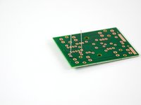
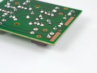
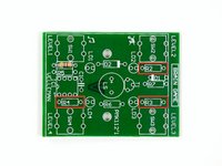
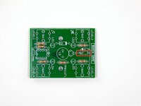
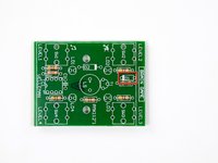
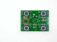
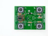
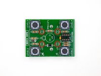
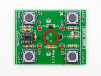
Why is it called through-hole, you ask? You'll notice the circuit board has a bunch of holes in it, each with a copper trace on the underside of the board. The leads of each component are fed through these holes (hence through-hole) and soldered to the copper trace.
 Pergunte ao FixBot
-
-
-
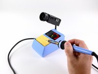
The most important tool for any soldering job? Your soldering iron, of course! For this procedure we'll be using the soldering station that we sell in our parts and tools store.
-
For this project, you won't want your soldering iron to exceed 40 watts at the tip. For our station which draws 50 watts of power from the wall, it is safe to crank it up all the way to max.
-
If this is the first time you're firing up your soldering iron, you may notice some smoke and a not-so-pleasant scent. Don't worry; this is just the coating on the tip burning off. Wait a couple minutes for the soldering iron to stop smoking.
-
Before you start soldering, be sure to dampen your cleaning sponge. A dry sponge will just get burned.
-
-
-
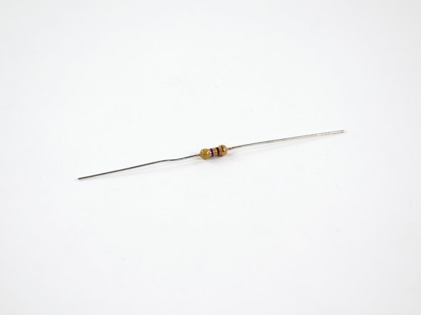
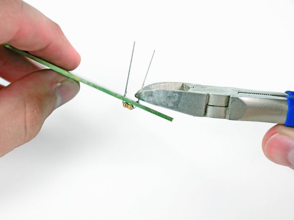
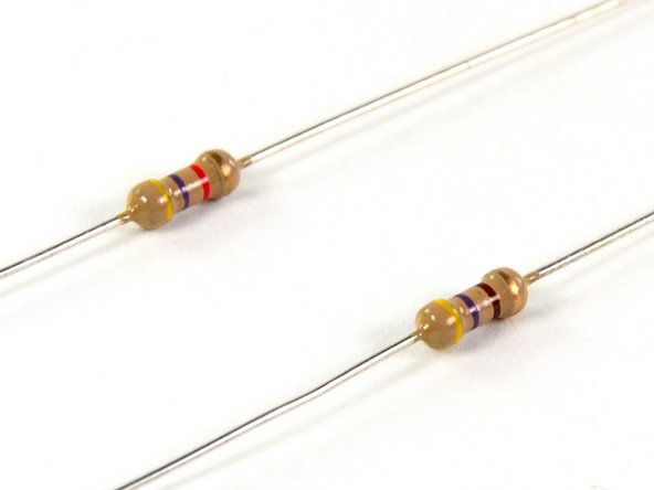
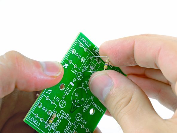
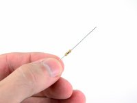
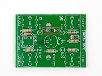
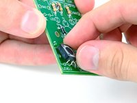
We'll start with resistor R1 in your kit, which has yellow, purple, brown, and gold rings on it (more on what these colored rings mean later).
-
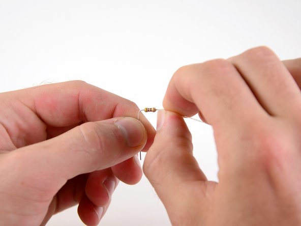
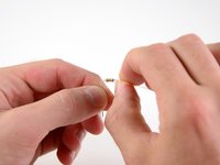
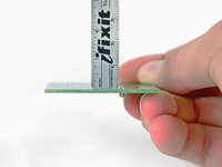
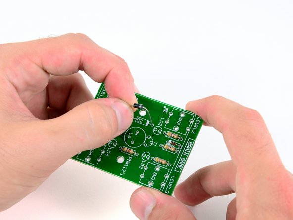
Bend the leads of the resistor to 90o angles about 1.5 mm away from the body of the resistor.
-
-
-
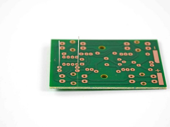
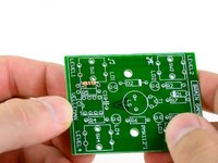
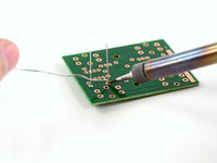
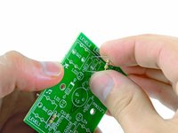
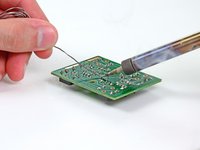
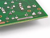
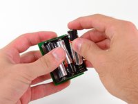
Place the leads of the resistor through the holes on either side of the rectangle marked R1 on the circuit board.
-
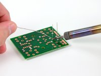
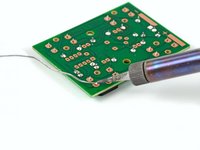
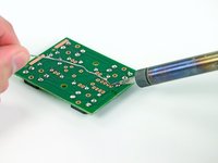
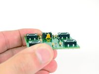
Turn the board over so that the copper traces are facing up and the resistor leads are pointing straight up in the air, as seen in the second picture.
-
-
-
You must be itching to throw down some molten metal by now; however, you still need to prepare the tip of your soldering iron.
-
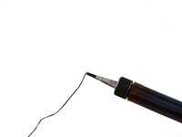
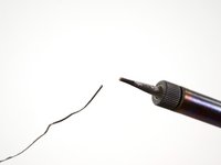
Now that your soldering iron's tip is hot, clean it by melting a small amount of solder directly on the tip and wiping it off on your damp sponge.
-
Melt another small ball of solder onto the tip of the soldering iron, but do not wipe it off. This is called "tinning" the iron, and will improve heat conductivity, allowing you to solder more quickly and efficiently.
-
-
Ferramenta utilizada neste passo:FixHub Smart Soldering Iron$79.95
-
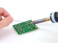
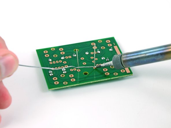
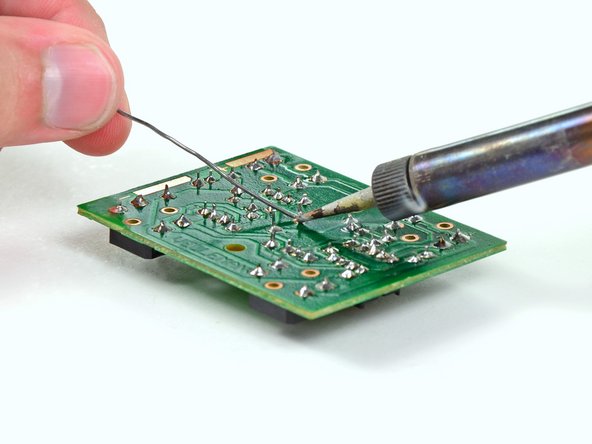
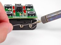
Here we are: the moment of truth. It's time to get that solder flowing.
-
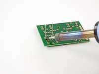
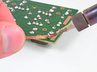
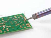
Set the tip of the soldering iron on the two parts to be connected. In this case, that's the resistor lead and the copper trace on the circuit board.
-
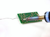
Touch your solder to the tip of your soldering iron to melt it onto the joint. Don't hold it there for more than a second or two.
-
Quickly, but not frantically, pull both the soldering iron and the solder away from the joint.
-
Your solder joint should be shiny and conical, and not expand beyond the copper trace.
-
-
-
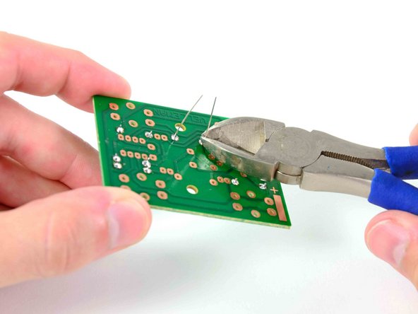
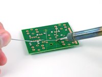
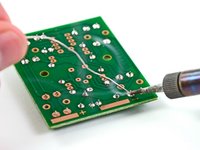
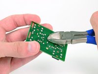
Use the same method above to solder the second resistor lead to the circuit board.
-
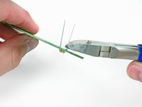
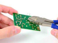
Cut the extra lengths of the resistor leads with a pair of wire cutters. NASA workmanship standards state that any length up to 2.29 mm is acceptable.
-
-
-
We all make mistakes, especially when trying something new. Soldering is no exception, so here's what to do when one of your soldered joints comes out less than ideal.
-
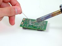
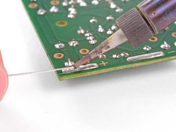
Lay a strand of desoldering braid over the solder in question. Press the tip of the soldering iron firmly onto the desoldering braid. This will heat up both the solder and the braid.
-
The solder should flow from the joint to the desoldering braid. After the solder flows into the braid, remove it and the soldering iron from the board. You should now have a clean contact to start over with. Use wire cutters to cut off the used end of the desoldering braid.
-
-
-
So, what are resistors, and why do we care about them? Resistors are components used in circuitry to control the amount of current flow. The more resistance a resistor has (measured in Ohms, Ω), the less current it allows to flow.
-
The colored bands on a resistor are the key to determining the resistance of that particular resistor. A resistor color code chart will come in handy here.
-
If there are four bands on your resistor, the first band to locate is the red, gold, or silver band on one of the swollen ends; these are called tolerance bands. Since our resistors have gold bands, we know the actual resistance is within ±5% of the nominal value
-
The next step is to determine the nominal value of your resistor. Starting at the opposite side of the tolerance band and moving from left to right, there are three colored bands. The first two color bands correspond to a number (0-9), and the third band is the multiplier band, which corresponds to a specific power of 10.
-
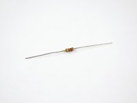
Looking at the top resistor shown, we see yellow, violet, and red bands. Consulting a resistor color code chart shows us that those correspond to 4, 7, and 100, respectively, giving us a nominal resistance of 4,700 Ω.
-
-
-
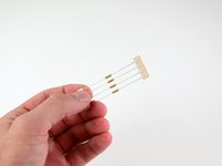
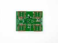
Install the three remaining 470 Ω resistors (yellow/violet/brown) into the terminals marked R2, R3, and R4.
-
-
-
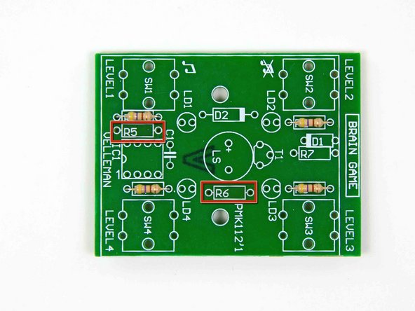
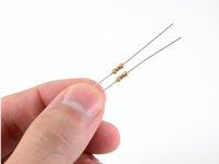
Fish the two yellow/violet/red resistors out of your kit.
-
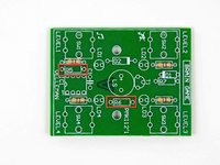
Install these two resistors into the R5 and R6 terminals on the circuit board.
-
-
-
Locate your single yellow/violet/black resistor.
-
Install this resistor into the terminal marked R7 on the circuit board.
-
-
-
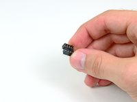
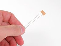
Dig around your kit a little more, and you'll find some new and exciting components with long leads attached to them.
-
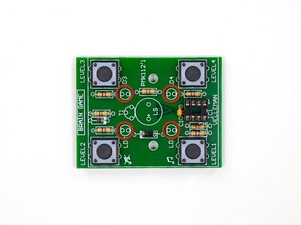
These are diodes—circuitry's "one way" signs. Their job is to make sure that current only travels in the forward direction, from anode to cathode, while blocking it from traveling in reverse. Current enters the anode (positive terminal) and leaves the cathode (negative terminal).
-
Since they only allow current to travel in one direction, it is rather pertinent that you install diodes with the correct polarity. The stripe on a diode signifies which side is the cathode.
-
-
-
-
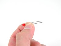
Bend the leads of the small red diode and insert them into the terminal marked D1.
-
Use the same method you used to solder the resistors to the board to install the diode.
-
-
-
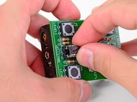
No game is really a game until there are buttons involved, so let's put those on the board next.
-
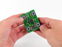
Insert the leads of the four buttons into the spots marked SW1 through SW4.
-
There is no particular orientation that the buttons must be installed in, as long as the leads are properly seated in their holes.
-
-
-
Solder each of the leads for each button.
-
The technique for soldering the buttons is the exact same as soldering the resistors and diodes, except that you do not need to cut any excess leads after soldering the joint.
-
-
-
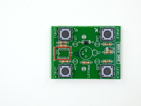
Next you will install the IC socket, also known as a CPU socket. IC sockets use a mechanical connection to connect a processor to a printed circuit board. These sockets allows the processor to be easily replaced without the risk of damage associated with soldering processors directly to a circuit board.
-
Stick the eight leads of the IC socket through the holes in the rectangle marked IC1. Make sure that the semi-circle on the top of the socket lines up with the semi-circle printed on the edge of the rectangle on the circuit board.
-
Turn the board over and solder the eight leads of the IC socket to the board. Similar to soldering the buttons, there is no need to trim any excess off the leads.
-
-
-
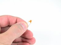
The next component we will be installing is the yellow capacitor. Capacitors store electrical charge, and are helpful when a circuit needs a quick shot of energy to illuminate a light or make a beep.
-
Capacitors are measured (in Farads) as the ratio of the electrical charge on each conductor to the potential difference between them. This capacitor is a 1 µF capacitor.
-
Install the capacitor in the terminal next to the IC socket marked C1. Soldering the leads of a capacitor follows the same through-hole procedure used thus far.
-
-
-
The next components to install are the LEDs. Light emitting diodes are used in all sorts of electronics to provide bright, different colored lights.
-
The four LEDs belong in each of the four terminals marked LD1 through LD4.
-
When installing the LEDs, insert the shorter of the two leads into the hole next to the flat part of the printed circle.
-
-
-
Solder each of the LEDs to the circuit board and cut the excess off each lead.
-
-
-
Another cool electrical component‽ How exciting!
-
Transistors are used to amplify and/or switch electrical signals. This means that they can either increase an input voltage, or be used as electronic on-off switches.
-
The important thing to pay attention to when installing a transistor is that you solder each lead to the correct spot, because each one has a different purpose.
-
One is used as the current source.
-
One is used as a gate.
-
One is used as a current output.
-
-
-
Locate the semi-circle labeled T1 and insert the three leads through the holes.
-
Solder the three leads to the board and cut the excess off the leads.
-
-
-
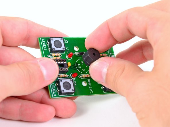
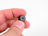
Obviously, your solder creation needs to have a super sweet sound system ... or this speaker. Close enough, right?
-
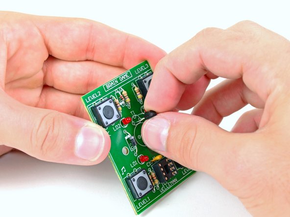
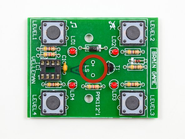
Insert the leads through the holes located in the circle labeled LS, making sure to match up the positive terminals.
-
-
-
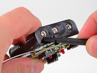
Bonus! You thought you were just learning how to through-hole solder, but Included with this kit is a complimentary intro to surface-mount soldering. Surface-mount soldering is commonly used to attach batteries to circuit boards in some devices, such as iPods.
-
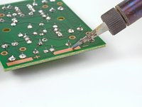
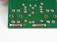
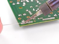
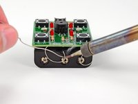
Set the tip of your soldering iron on the large copper negative solder pad. This will allow heat to conduct through the solder pad, making soldering easier.
-
Touch your solder to the tip of the soldering iron and keep feeding it until you have a smooth, convex solder dome on the copper pad.
-
-
-
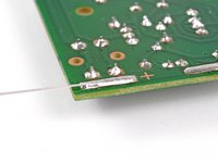
Repeat this process for the positive solder pad.
-
You should end up with two long, smooth, convex domes of solder.
-
-
-
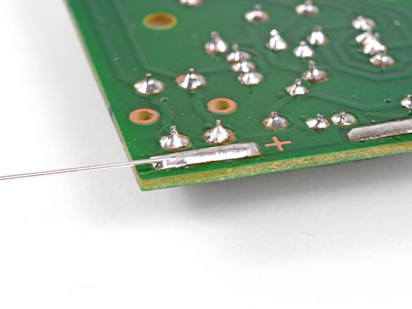
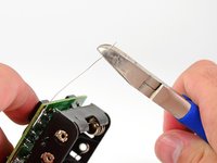
No, you weren't ripped off; those two leads aren't supposed to have any components in the middle of them.
-
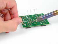
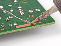
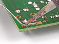
To solder the battery leads to the circuit board, set the tip of the soldering iron on the solder that's on the positive pad.
-
When the solder begins to melt again, quickly insert the end of the lead into the melted solder so that the lead hangs off the side of the board, as shown.
-
Remove the soldering iron and let the solder cool around the lead.
-
-
-
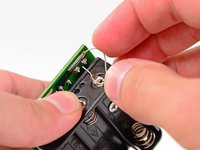
Repeat the surface mount soldering procedure for the negative battery terminal lead. Be sure to install the lead so that the excess wire hangs off the opposite side rather than the positive terminal lead.
-
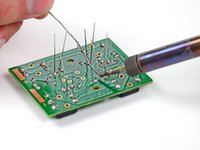
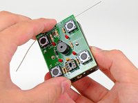
Now that you have installed whiskers on your circuit board, it's time to pet it and buy it a scratching post. Wait, that's not right . . .
-
-
-
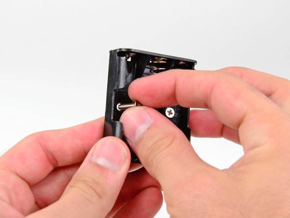
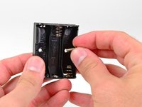
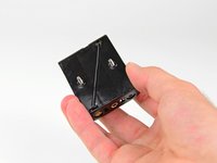
Insert the two Phillips screws through the holes in the underside of the battery compartment.
-
-
-
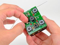
Place two fingers of one hand over the screw heads.
-
Keeping your fingers on the screw heads to hold them in place, grab the battery compartment with your thumb and flip it over. The screw threads should protrude out of the top side of the battery compartment.
-
-
-
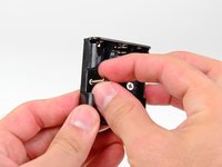
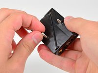
Use your free hand to place the two metal spacers over the screw threads (one per screw).
-
-
-
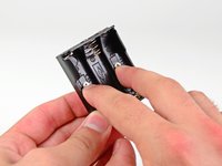
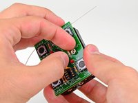
Continue holding the screws in place and set the circuit board on top of the battery compartment so that the two screws are fed through the holes on either side of the speaker.
-
Hand tighten the two nuts onto the battery compartment screws.
-
-
-
Place a 5.5 mm nut driver or socket over one of the battery compartment screw nuts.
-
Turn the circuit board over.
-
Use one hand to hold the socket in place and tighten the battery compartment screw with a Phillips #2 screwdriver.
-
Follow the same procedure to tighten the other battery compartment screw.
-
-
-
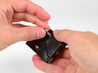
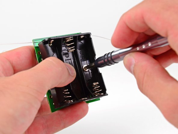
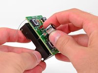
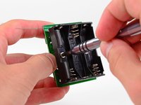
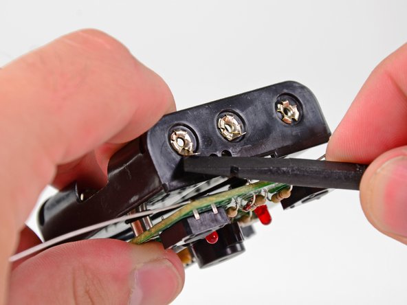
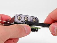
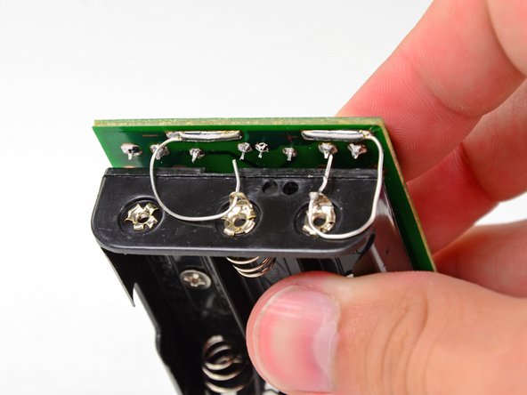
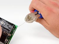
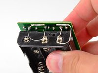
Use a spudger to pry the metal rings on the battery terminals up so that they perpendicular to the battery terminals.
-
-
-
Use a pair of wire cutters to remove about an inch of the positive terminal surface mount lead.
-
Bend the lead around and through the positive ring terminal on the battery compartment.
-
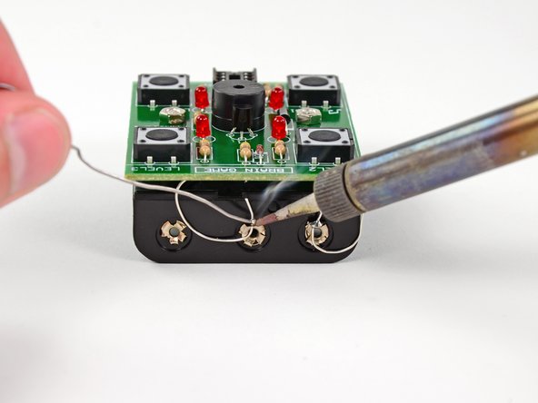
Use your now perfected through-hole soldering skills to solder the lead to the battery terminal.
-
Cut off any excess lead.
-
-
-
Repeat the same procedure for the negative battery terminal lead.
-
-
-
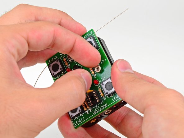
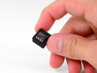
The final component to install on the circuit board is the central processing unit, or CPU—the brains of the Brain Game.
-
One end of the CPU has a small notch in it. When installing the CPU, make sure that this notch lines up with the cutout on the IC socket.
-
Install the CPU by pressing the eight pins into their respective holes in the IC socket.
-
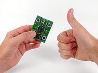
Congratulations, you have completed the Level 1 Through-Hole Soldering Kit!
-
-
-
Install three AA batteries in the battery compartment.
-
Upon inserting the final battery, the four LEDs should start flashing in a clockwise pattern. Congratulations, you did it!
-
To play the game, follow these instructions:
-
Remove one of the batteries. Then, reinsert the battery while holding the Level 2 button for no sound or the Level 1 button for sound. Release the button a couple seconds after the battery is inserted. The game will eventually power off on its own. To wake it up to play, press either the Level 1 button to play with sound, or the Level 2 button to play without sound.
-
As the LEDs blink in a clockwise rotation, press one of the four buttons to select the level of difficulty (printed above or below the buttons).
-
After selecting your level, the game begins. It is a typical Simon Says-like memory game. The LEDs will flash one light, then you have to click that button. Then it will flash two lights and you have to click those two buttons in order.
-
The game progresses until you mess up the pattern or take too long to respond.
-
Have fun! And be sure to tell us all about your high scores in our Story section.
-


Cancelar: não concluí este guia.
111 outras pessoas executaram este guia.

10Comentários do guia
Couldn't the CPU just be soldered in directly, instead of using the socket, or would this cause damage or something?
Yes you can, but it’s not a good idea. If you hold the soldering iron on the chip for too long, you might overheat it to the point of causing damage. This isn’t a problem for someone experienced with soldering, but it could be a problem for a beginner. Using a socket avoids the problem.
Thanks for a great tutorial, but apparently the design for the battery compartment has changed since this was made. It now comes with just one bendable lead on the top end and one on the bottom end of the compartment, which makes soldering to the battery compartment less straight forward. seems like it might be a manufacturing error. I got a replacement sent to me when I realized this, thinking it was a one-off, but the replacement has the same design. It's weird because even the (much less descriptive) guide that comes with the set shows 2 bendable leads on one end like yours.
I am having the same exact problem. My wife got this for me as an anniversary present. I am at the part where you are supposed to do the soldering to the battery box. Needless to say, I am stuck. I am thinking I’m going to have to find a piece of wire with insulation on it that I can use in the place of the junk that is in the box for this connection to the positive terminal. It’s the only solution I can think of, anyway.
The kits as they come will not be able to have the two small bendable leads attach to the battery pack. In the guide it shows both leads attaching on the same side of the box but the kit has a battery box with the leads on opposite sides. I ditched the bendable leads entirely and just used some extra with I had to complete the connection. Not a huge problem if you have spare wire but annoying.