Ir para o conteúdo principal

Released November 2016, the PS4 Pro features upgraded hardware for 4K gaming and improved PSVR performance.

384 Perguntas Visualizar todos

Power supply connector broken, need infos

Hi,

My friend give me a PS4 Pro bcs he broke the power supply connector on the logicboard.

Im want to do the repair by myself, i have checked the tools but i m not sur what i have to do, its my first time.

Someone before me try the repair but he failed and this was a dirty job.

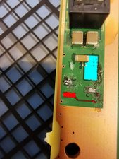
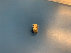
So my question is, what i need to do for soldering, i have seen all the ytb tutos, read all posts on this forum but i can't say if i need to do a jumper and what i need to "link" with the jumper, if i need to do some (unknow) tricks or just clean the logicboard connector and solder the white plastic connector?


Thank for your time in advance

Block Image

EDIT: clean pic

Block Image

Block Image

EDIT:
After some research the Purple and Blue work (checked with multimeter) but i can't (no understanding) get the Black nor the Red work with my multimeter, i don't understand how i can create a "bridge" for test.

Block Image

Responder a esta pergunta Também tenho esse problema

Esta é uma boa pergunta?

Pontuação 1
Adicionar um comentário

3 respostas

Pergunta mais útil

First things first, MAKE SURE YOU ORIENT THE SOCKET CORRECTLY. You do not want to reattach this backwards. Also, you should clean up the area before sharing pics. This one LOOKS relatively straightforward, but I can't be certain because of the grime left.

Use a bit of non-conductive epoxy to glue the socket to the board in a way that the 2 pads that still look good are lined up. Then solder those two pins in. One of the remaining pins looks to have been attached to a bit of a plane indicated with cyan in my modification of your image here. In red, we see the trace that goes to the other pad.

Using a scalpel, scrape away a bit of the solder mask on that plane and on that trace to expose some copper. Then use 0.2-0.3 mm wire to solder in a jumper between the newly exposed copper and its associated pins. Not the easiest "first job," the but reward is probably worth the risk. And hey, you can't really make things worse unless you attach the socket backwards and apply power to it.

Block Image

Esta resposta foi útil?

Pontuação 3

2 comentários:

Might be a bit easier to solder a jumper wire from the power pin directly to the end of the SMD device overhanging the cyan pad, but your directions are spot on, @dushku. Good answer!

por

Thanks, now i understand more.

Yes it worth the risk but i do that for "fun" i like things like this, ofc i hope it work.

por

Adicionar um comentário

a soldering iron, solder, flux, solder wick, uv mask, uv light and enamelled wire. https://www.youtube.com/watch?v=EmNf4-Fr...

Esta resposta foi útil?

Pontuação 2

1 comentário:

Thank you, very useful!!! need some stuff (and time)

por

Adicionar um comentário

@papz I agree with @tech_ni on all of what was said. I wonder if you have soldered on a board before. this may look easy (and it could be) but requires some decent soldering skills. If you have not done any board soldering, I'd recommend that you get materials listed by daniel and practice on an old scrap board first. Anyhow, the "power socket ways" is a great resource but it'll complicate things for you. I your case, you want to first off, clean "the mess". Use your soldering iron to fix the #2 pin connector, clean your board with isopropyl alcohol and let's review what you have. I see number 2 with a full solder pad and number 3 with a partial solder pad. There will not be enough "meat" to hold the connector. My concern is that you are going to tear it off the moment you connect the wire. Consider two possible solutions. One is to attach the wires directly to the board and then the connector to the end of those (like a pig tail situation) The other possible solution would be to apply some adhesive to the connector to keep it bonded to the board (After soldering it to the board of course). Keep your jumpers short. Pin 1 can come right of the capacitor next to it. 2,3, and 4 can be soldered to just at the end of the traces. Remember keep the enameled wire size down. You do NOT need thick wires for this.

Esta resposta foi útil?

Pontuação 2

2 comentários:

Thank you very much,

I agree with you, I need to learn more and practice to do a good job.

Now with the other answers I have a good starting pack.

por

@papz sounds like you got this :-) Best of luck to you and let us know how it works out.

por

Adicionar um comentário

Adicionar a sua resposta

Papz será eternamente grato(a).
Exibir estatísticas:

Últimas 24 horas: 1

Últimos 7 dias: 6

Últimos 30 dias: 23

Duração total: 662