Introdução
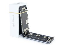
Follow the steps in this guide to replace the logic board in an iPhone 6s.
It's important to note that each iPhone's logic board and Touch ID fingerprint sensor are paired at the factory, so replacing the logic board will disable Touch ID unless you also install a replacement home button that has been properly paired to your new logic board.
You can also use this guide for reference to replace the logic board EMI shield stickers.
O que você precisa
-
-
Remove the two 3.4 mm P2 Pentalobe screws on the bottom edge of the iPhone, on either side of the Lightning connector.
-
-
Ferramenta utilizada neste passo:Clampy - Anti-Clamp$24.95
-
Pull the blue handle backwards to unlock the Anti-Clamp's arms.
-
Slide the arms over either the left or right edge of your iPhone.
-
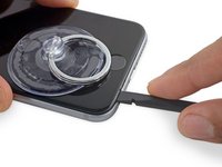
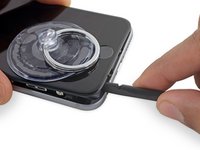
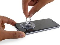
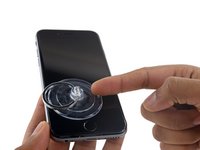
Position the suction cups near the bottom edge of the iPhone just above the home button—one on the front, and one on the back.
-
Squeeze the cups together to apply suction to the desired area.
-
-
Ferramenta utilizada neste passo:Clampy - Anti-Clamp$24.95
-
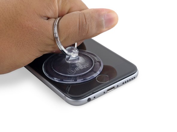
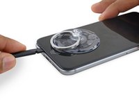
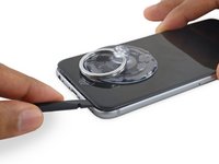
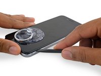
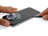
If you don't have an Anti-Clamp, follow the next three steps to use a suction handle.
-
Apply mild heat to the lower edge of the iPhone using an iOpener or hair dryer for about a minute.
-
-
-
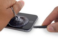
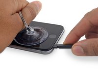
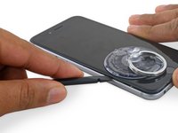
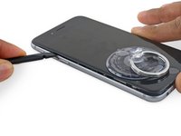
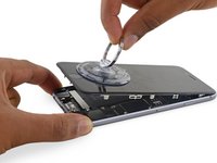
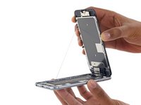
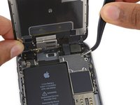
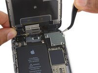
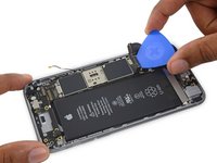
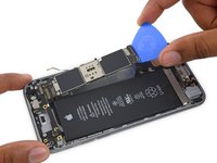
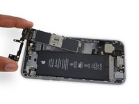
Gently grasp the display assembly and lift it up to open the phone, using the clips at the top of the front panel as a hinge.
-
Open the display to about a 90º angle, and lean it against something to keep it propped up while you're working on the phone.
-
Add a rubber band to keep the display securely in place while you work. This prevents undue strain on the display cables.
-
-
Ferramenta utilizada neste passo:Magnetic Project Mat$19.95
-
Remove two Phillips screws securing the battery connector bracket, of the following lengths:
-
One 2.9 mm screw
-
One 2.2 mm screw
-
-
-
-
Remove the following four Phillips screws securing the display cable bracket:
-
Three 1.2 mm screws
-
One 2.8 mm screw
-
-
-
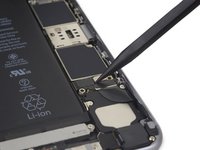
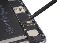
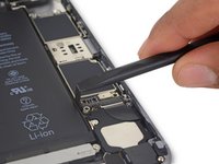
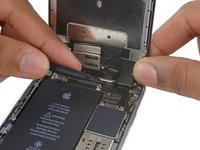
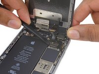
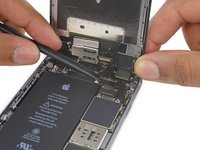
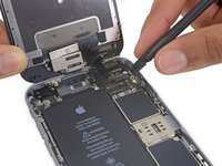
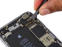
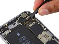
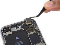
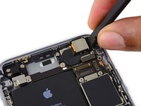
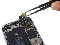
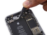
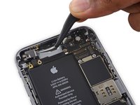
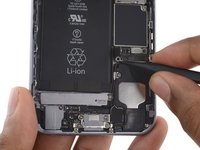
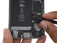
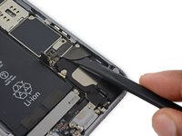
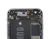
Use the flat end of a spudger to disconnect the rear camera from its socket on the logic board.
-
-
-
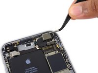
Insert a SIM card eject tool or a paperclip into the small hole in the SIM card tray.
-
Press to eject the tray.
-
-
-
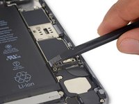
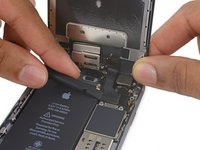
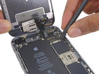
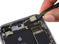
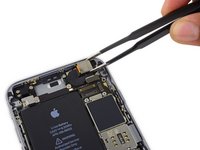
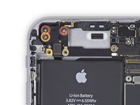
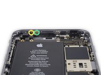
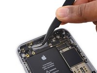
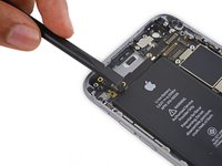
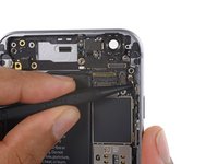
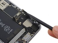
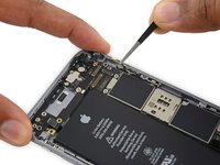
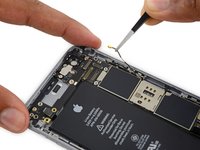
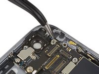
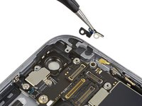
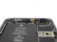
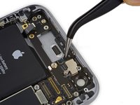
Remove the two 2.3 mm Phillips screws securing the upper component cable connector bracket.
-


To reassemble your device, follow these instructions in reverse order.
To reassemble your device, follow these instructions in reverse order.
Cancelar: não concluí este guia.
230 outras pessoas executaram este guia.

33 comentários
So all the logic boards come with the components installs? Like the High band PAD, power amplifier avago, power amplifier Skyworks, power amplifier TriQuint, LTE modem Qualcomm, and lastly the Apps processor Apple SoC stacked on Elpida RAM. Here I thought you had to buy them.
I'm also assuming that some don't. I would like to know that alternative.
Yup! The SSD is a flash memory chip hidden underneath an EMI shield on the logic board. You can see it in our teardown.
Um, no, actually the NAND/ssd/flash/storage chip is the big Toshiba one in the middle, it’s the one next to the line of capacitors, and is not under the shields. there are shields on either side of it. Look at the teardown page you linked to yourself and you will confirm what I’ve said.
great guide worked perfectly, had some minor water damaged internals with a completely good logic board, replaced it in a 16g pos basically have a brand new 128g 6s