Introdução
Follow this guide to replace the motherboard on a Microsoft Surface Pro 4.
There is a significant chance that you may break the unreinforced and fragile display panel during this procedure. Be sure to apply adequate heat and be extremely careful while slicing through the adhesive. Wear safety glasses in case the glass shatters.
Applying new thermal paste during reassembly may improve the performance of your Surface. If you wish to do that, make sure you have new thermal paste and either high-concentration isopropyl alcohol or a specialized thermal paste cleaner.
O que você precisa
-
-
If your screen glass is cracked, keep further breakage contained and prevent bodily harm during your repair by taping the glass.
-
Lay overlapping strips of clear packing tape over the Surface’s screen until the whole face is covered.
-
Do your best to follow the rest of the guide as described. However, once the glass is broken, it will likely continue to crack as you work, and you may need to use a metal prying tool to scoop the glass out.
-
-
-
Heat an iOpener and apply it to the right edge of the Surface's screen for two minutes.
I have done dozens of Surface Pro tablet repairs; if your screen is cracked or chipped AT ALL, you WILL make it worse. Plan on replacing it. Even if it's not cracked or chipped, the likely hood of removing this screen without damage (LCD separation or heat marks in the corners) is very low. Ive tried everything from hot plates to heat mats and the iOpener and nothing is reliable enough. I found that using my Warner heat gun set at 800*c and working on half an edge at a time with a LOT of 91% alcohol in a drip bottle along the edge, along with a very thin guitar pick (not the ones sold here, they are too thick) is the trick to loosening the glue. Work on the side and bottom first. The top is going to be the hardest as the adhesive will stick to the wifi/bluetooth antenna and you WILL tear them (Ive had to replace a fair amount of them). There's a delicate trick to doing it, but it's too hard to describe. If you've never done this repair before, I do not recommend it; find a professional.
Hi, thanks for the information, Very valuable.
I'm about to do this because my battery and fan aren't working.
There's no way anybody can fix it properly near me. Got any other tip to try not to break the screen and or any flex?
I've done works like this on small tablets and phones, but never this pc. I'll try to go slow.
Thanks again for your experience information.
-
-
-
Take note of the screen adhesive layout before continuing:
-
These areas only contain adhesive and are safe to cut.
-
The display board and flex cables sit here close to the edge. Cut carefully and don't insert the pick more than 1/8 inch (3 mm).
-
Fragile antenna cables lie under this part of the screen. Carefully follow the procedure in step 13 to avoid damaging them. The adhesive is also the thickest here.
The bottom red section is narrow and not as thick as the bevel indicates. I went too deep with my tool and cut through a ribbon thinking that I could send my tool as deep as the black bevel edge. its like half that.
I did a screenshot of this image to always see it while progressing through the steps and did exactly the same mistake. I read every comment in the steps below but yours only now :( On my device it's 5mm from the edge of the screen glass to the ribbon.
I cut through as well, but was able to carefully solder the edges together enough to make a connection - works fine.
The sensitive areas are on the opposite side from the easy areas - YET - there is nothing in the diagram to indicate which is the keyboard attaching edge or any other identifier.
-
-
-
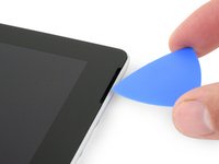
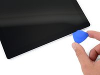
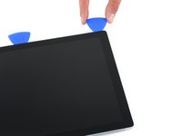
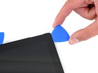
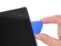
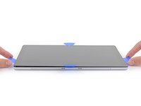
Insert an opening pick into the top-right speaker cutout on the screen and slide the pick between the glass and speaker grille.
-
-
-
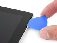
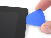
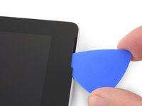
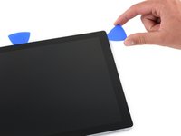
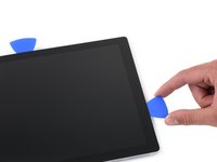
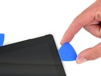
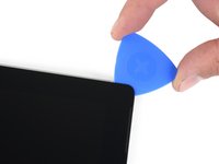
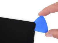
Slide the pick down the right edge of the Surface to slice through the adhesive under the screen.
-
Leave this opening pick in the right edge to prevent the adhesive from resealing.
-
-
-
Reheat your iOpener and apply it to the bottom edge of the Surface's screen for two minutes.
-
-
-
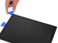
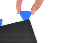
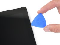
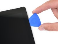
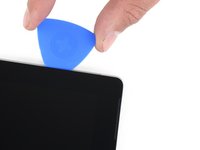
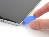
Insert a new opening pick into the bottom-right corner and slide it around the corner toward the bottom edge.
-
Slide the pick along the bottom edge of the Surface to cut through the screen adhesive.
-
Leave this pick in the bottom edge to prevent the adhesive from resealing.
Yep. I scratched the corner of the LCD with the pick. Take the warning seriously folks! It’s really easy to do.
The warning says to not insert it more than 12mm but it should be not more than 5mm. There is a ribbon/display connection at the bottom and i damaged it.
Exactly! The bezel is much smaller at the bottom side and you will hit the LCD if you push deeper than 6mm.
mowny -
-
-
-
Reheat your iOpener and apply it to the left edge of the Surface's screen for two minutes.
-
-
-
Reheat your iOpener and apply it to the top edge of the Surface's screen for two minutes.
-
-
-
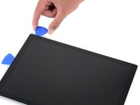
Round the left corner with the opening pick and slide it along the top edge of the Surface. Stop when the pick is 2.75 inches (70 mm) away from the left edge.
The right antenna is kind of P shaped (rotated 90° to the right) with the small end facing the middle. I'd suggest to stop at the middle when loosening the left antenna and to do the same thing coming from the right.
-
-
-
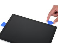
Insert the point of a pick under the screen where you just stopped cutting. Don't insert the pick deeper than the edge of the bezel.
-
Carefully roll the pick to the right, pressing the long edge of the pick into the screen adhesive underneath the bezel, cutting the adhesive as you go. Don't slide the pick along the edge of the Surface.
-
Repeat this motion of inserting the point of the pick where you just cut, and rolling to the right all along the top edge of the Surface, until the pick is 2.5 inches (64 mm) from the right edge of the Surface.
Bij mijn exemplaar bleek het onmogelijk om de bovenrand volgens de aanwijzingen los te maken. Ik heb de boel vele keren opgewarmd en ben meerdere malen met het plectrum langs de rand gegaan. Maar er beleef iets hardnekking vastplakken. Ik moest uiteindelijk de lijmverbindingen los maken zoals bij de andere randen. Achteraf bleek dat bij het gedeelte waar de antennes zaten het frame en het scherm volledig met elkaar verlijmd zaten met de antennes er tussen. Dat kostte me uiteindelijk de antennes. Gelukkig geen schade aan andere zaken. Niet zo'n grote ramp want ik kon nog antennes bestellen. Maar hou er rekening mee.
-
-
-
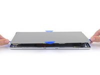
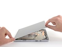
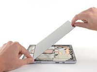
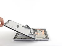
Very slowly lift the screen assembly away from the Surface case. If you encounter any resistance, stop and check that all the adhesive is separated.
-
Use an opening pick to cut through any remaining adhesive.
iFixit should show the closeups of the edges of the chassis, after the screen has been removed showing where the glue needed to be cut and the proximity to other internal parts so the repair tech can anticipate what they can't see and avoid being too aggressive. Show the difference between a clean removal vs one that was problematic in breaking the seals around the edges.
-
-
Ferramenta utilizada neste passo:Tweezers$3.99
-
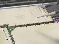
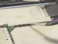
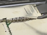
Use one tip of a pair of angled tweezers to pry up the EMI shield from the gaps between the "teeth."
-
Repeat this procedure at different points around the perimeter of the shield until it is free.
-
-
-
-
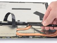
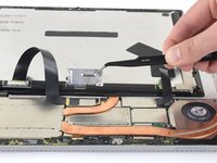
Use your tweezers to remove the two EMI shields covering the display cable connectors.
-
-
-
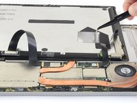
Remove the screen from the Surface.
-
During reassembly, pause here and follow this guide to replace the screen adhesive.
-
-
-
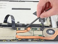
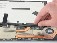
Use a T5 Torx screwdriver to remove the four 4.5 mm screws securing the antenna support bracket.
This screw bit was not included in the battery replacement kit. Only Philips and Flathead were included.
This Torx bit was not included in the battery replacement kit. Only a Philips and Flathead bit
used phillips bit and stripped screws
-
-
-
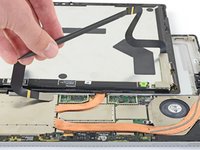
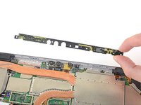
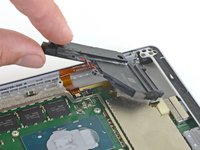
Carefully remove the antenna support bracket.
I had ripped through 2 of the 3 antennas when cutting through the top adhesive. Not sure how anyone removes this display without ruining at least one of them.
I saw on Reddit this post: https://www.reddit.com/r/techsupportmacg...
It works perfectly! My wifi was one that was cut. It’s now made of aluminum foil and is pulling down 147Mbps and pushing 80.88Mbps up.
A ce stade il semble important de faire attention au micro. Pour ma part, il avait un résidu de colle entre celui-ci et le support à retirer.
On my device the mic is glued to the antenna board. I'd recommend to detach it's ribbon cable from the motherboard before removing the antenna board
what is this clear round plastic piece that came off with the display glue? cant add picture
-
-
Ferramenta utilizada neste passo:Tweezers$4.99
-
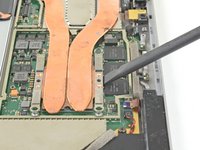
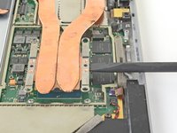
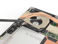
Insert one point of a pair of pointed tweezers into a gap in the corner of the EMI shield covering the heat sink.
-
Use the tweezers to pry the EMI shield away from the motherboard as much as you can without bending it. Do not remove it yet.
-
-
-
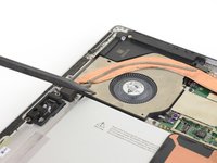
Use a T3 Torx screwdriver to remove two screws from the heat sink:
-
One 2.4 mm screw along the top of the rectangular plate covering the battery.
-
One 2.2 mm screw along the bottom of the rectangular plate covering the battery
La première vis de 2,4 est une Torx 4, pour ce qui me concerne et non pas une Torx 3.
Attention la deuxième vis est bien une TORX 3
Remarque : La boite à outil "Essentiel electronics Toolkit - Grade B (ref EU145571-1)" ne contient pas l'embout T3
Pour ma part j'ai utilisé donc le T4 en forçant un peu. Pas cool ;-(
-
-
-
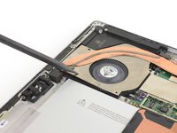
Use a Phillips screwdriver to remove three 2.4 mm screws securing the fan.
-
Use a T5 Torx screwdriver to remove the final 4.4 mm screw securing in the fan cover.
These screws were in a different area on my Surface, Pro 4 bought at release. The fan was visible and attached to the heat sink. Remove the two torx screws on the fan housing. No need to remove the Philips head screws that secure the fan.
Sorry I’m super brand new to the game. I don’t know the difference between 1.5mm Torx T4 and 3.0mm Torx T4. I look under tools I need to buy, and the tool kits only say Torx T4 or T5, without the milimeters dimensions.
Je fais écho au commentaire de vennic, les longueurs indiqués en mm sont les longueurs des vis et n’impactent pas les tournevis à utiliser. Bien ranger les vis par longueur permets de mettre les bonnes vis aux bons endroits lors du remontage de l’appareil.
Cajuteq -
The fan connector on mine was held in place by a white clamp on the side closest to the middle of the chassis. The long edge toward the middle flips up to vertical. That frees up the fan connector. Likewise for the black “wire” connector right beside it.
As previously mentioned, the fan should be disconnected (look at step 36) BEFORE you remove the fan/heat sink assembly. Ive done DOZENS of these repairs and the fan has always been part of the heat sink assembly.
I did all of this, now surface won't turn on. Any ideas?
-
-
-
Use a T5 Torx screwdriver to remove the heat sink screws surrounding the CPU in the following pattern, one turn at a time, until they're free.
-
Screw 1
-
Screw 2
-
Screw 3
-
Screw 4
These screws were T5 Torx in mine, not T3 as in the instructions.
T5 Torx screwdriver is correct.
T4 Torx for me.
What does one turn at a time mean?
One turn for the "red" screw, one for the orange, one for the yellow, then green and now again one turn red, orange, yellow, green ... This cross pattern distributes the pressure evenly .
VauWeh -
I think I need a T6 torx screw the screwdriver is not working for these screws
-
-
-
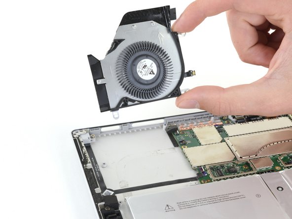
Use the flat end of a spudger to gently pry the heat sink straight up and off of the CPU.
-
-
-
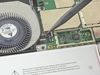
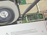
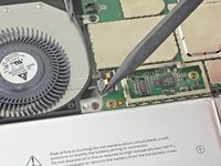
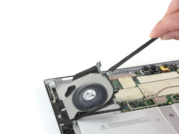
Insert the pointed end of a spudger into a screw hole in the fan shield and lift up to separate it from the fan.
The fan should be disconnected (look at step 36) BEFORE you remove the fan/heat sink assembly. Ive done DOZENS of these repairs and the fan has always been part of the heat sink assembly.
These instructions were correct for my Surface. The fan cover was attached to the heatsink but the fan was not.
-
-
Ferramenta utilizada neste passo:Tweezers$4.99
-
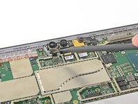
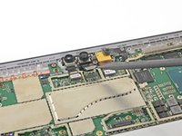
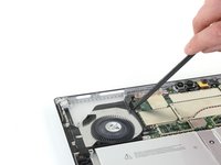
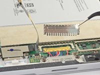
Insert one point of a pair of pointed tweezers into a gap in the corner of the EMI shield covering the camera connectors.
-
Use the tweezers to pry the EMI shield away from the motherboard as much as you can without bending it.
-
Remove the EMI shield.
-
-
-
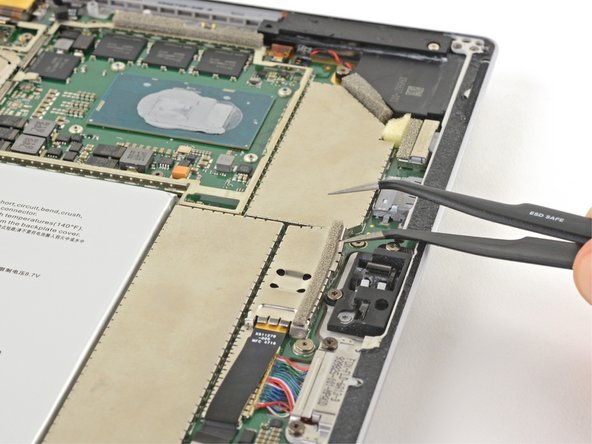
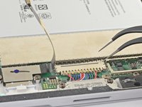
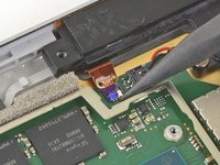
Pry up with the pointed end of your spudger to disconnect all three camera cables from the motherboard.
Missing the part to disconnect the ribbon to the left of the cameras, luckily, it disconnected by itself when I removed the motherboard.
Yes that's very important (white and blue socket on photo) !
I forgot to reconnect it on reassembly (unluckily, it doesn't reconnect by itself ;o)
Phil68 -
-
-
-
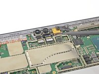
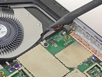
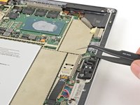
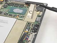
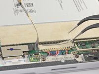
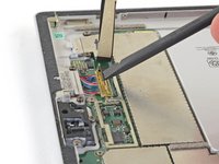
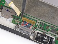
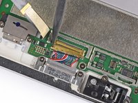
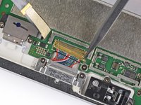
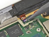
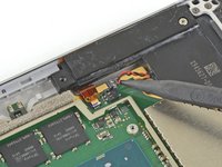
Use the pointed end of your spudger to unlock the ZIF connector securing the volume/power button cable.
-
Gently slide the volume/power button cable out of the ZIF connector.
While you're here, you'll want to disconnect the ZIF connector directly opposite from this one, which can be seen in the lower right of these photos, nearer the camera cable connection points. The guide doesn't mention removing that cable, but you'll need it removed before you can lift out the motherboard.
-
-
-
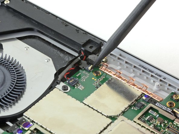
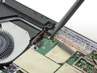
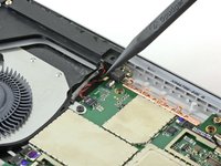
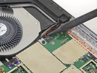
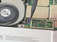
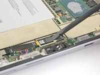
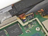
Slide the pointed end of a spudger between the speaker wires and the motherboard until it is resting against the speaker wire connector.
-
Carefully pry straight up on the speaker wire connector to disconnect it from the motherboard.
1. the picture can be misleading
2. use the flat end instead or you might damage the plastic part of the connector. see Microsoft Surface Pro 4 Left Speaker Replacement
-
-
-
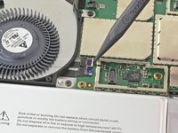
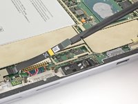
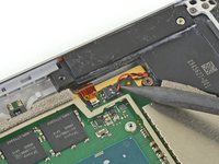
Use the pointed end of your spudger to unlock the fan and headphone jack ZIF connectors.
The fan should be disconnected when you removed the fan/heat sink assembly in Step 29 (which is NOT mentioned).
-
-
-
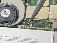
Use the pointed end of your spudger to gently slide the fan and headphone jack cables out of their ZIF connectors.
The fan should be disconnected when you removed the fan/heat sink assembly in Step 29 (which is NOT mentioned).
-
-
-
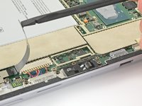
Use a T3 Torx screwdriver to remove the following screws from the fan:
-
One 2.5 mm screw with coarse threads
-
Two 2.4 mm screws
I didn't realize that one screw (red) here was different, and it looks like I put it in a different place during assembly, and the remaining screw, of course, did not hold. Be careful with the screws!
I have a question: can I buy a set of these screws for Surface Pro 4 to change the spoiled ones? I noticed that sometimes they get damaged on top and it is difficult to screw them on afterwards.
-
-
-
Use a spudger to lift one side of the fan.
-
Pick up the fan and remove it.
-
-
Ferramenta utilizada neste passo:Tweezers$4.99
-
Insert one point of a pair of tweezers into a gap in the edge of the EMI shield covering the microSD card reader cable and connector.
-
Use the tweezers to pry the EMI shield away from the motherboard as much as you can without bending it.
-
Remove the shield.
-
-
-
Use the flat end of your spudger to lift the microSD card reader's connector straight up out of its socket.
-
Lift the microSD card reader cable up and out of the way of the EMI shield covering the charging assembly.
It's probably best to remove the microSD card reader at this point. The guide never states to remove it, but it eventually disappears from the photos. Two T5 screws are all that are holding it down. Easier to take those out and remove the assembly than to try to remove the EMI shield underneath while also holding the ribbon cable out of the way.
Not necessary to remove the reader. When reinserting the motherboard, you can slide it easily enough underneath it. It may make it easier, but isn't necessary.
A ce stade, la nappe était coller sur le blindage. Pour ne pas trop plier la nappe, j'ai poussé la spatule. La colle n'était pas trop résistante.
-
-
-
Insert one point of a pair of tweezers into a gap in the edge of the EMI shield covering the charging assembly cable connector.
-
Use the tweezers to pry the EMI shield away from the motherboard as much as you can without bending it.
-
Remove the shield.
-
-
-
Use the flat end of a spudger to flip up the retaining lock securing the charging assembly cable connector.
-
-
-
Use a T5 Torx screwdriver to remove the two 3.1 mm screws securing the microSD card reader.
-
-
-
Use the pointed end of your spudger to unlock the ZIF connector between the processor and right speaker.
-
Disconnect the cable from the ZIF connector.
The removal of that cable is also much(!) easier after removal of the speaker, as there is more space for the cable to slide out (and later in)
This one broke during reassembling, so I could not fix the connector properly. I tried to find out what it is, but the only hint I found was, that it is some kind of antenna. I could not find out what kind of antenna. Anyway, after completion everything I needed worked fine: Bluetooth and Wireless LAN. I appreciate any hint about the purpose of this antenna.
That's my question too
Mj Ro -
Perhaps one of the two WiFi frequencies (2.4 or 5 GHz)?
Phil68 -
If it was indeed for Wi-Fi then wireless LAN would not work for one or the other freq,'s
I too broke the ZIF connector beyond repair. Hopefully its only related to the speaker on that side.
Has to be a better way...the snap in plug was being stubborn. The plug seat broke away from the circuit board. Now I only have the male and female ends and no way to easily solder back to the board.
-
-
-
Slide the pointed end of a spudger between the right speaker wires and the motherboard until it is resting against the speaker wire connector.
-
Carefully pry straight up on the speaker wire connector to disconnect it from the motherboard.
-
-
-
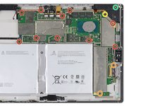
Use a T3 Torx screwdriver to remove the following screws from the fan and motherboard:
-
Ten 2.4 mm screws
-
Two 2.2 mm screws
-
Use a T5 Torx screwdriver to remove the two screws securing the right speaker:
-
One 4.2 mm screw
-
One 6.0 mm screw
Use a T5 Torx screwdriver to remove screw in left and right speaker.
BE CAREFUL! Use a T5 Torx screwdriver to remove an ADDITIONAL screw on the top corner of the right speaker. It should not take a tremendous amount of force to remove the speaker.
This screw is in the frame of the SP4. Mine was a T3.
An additional screw has been marked up and added to the original photo regarding the issues with the right fan removal. Thanks to the community for the feedback!
-
-
-
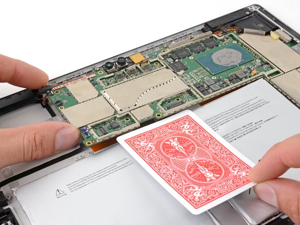
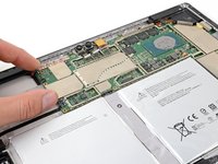
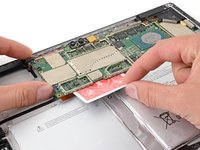
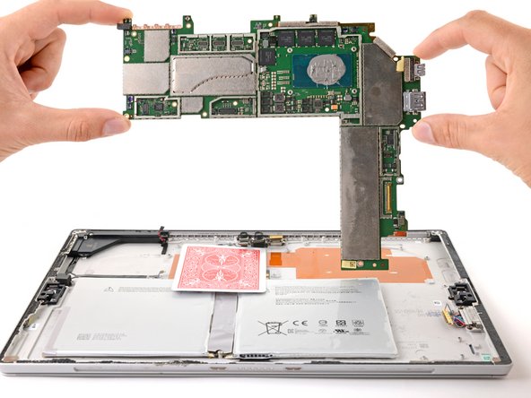
Slightly lift the left edge of the motherboard.
-
Insert a playing card or similar object between the battery connector and the motherboard.
Make sure "Insert a playing card" or "similar object" is "non-conductive" in nature and materials
-
-
-
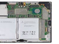
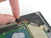
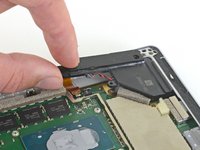
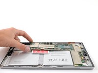
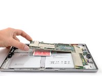
Grip the narrow section of the right speaker box and lift it up slightly.
-
Slide the right speaker back out of the chassis.
-
Remove the right speaker.
I didn’t read about the other T5 (about 6 mm) holding down the right speaker. It needs to be removed prior to this step.
You also need to remove a screw in the top right corner of the speaker
Yup there is an unmentioned t5 screw that the other comments catch
-
-
-
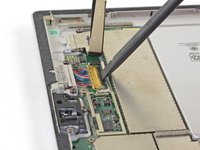
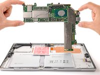
Remove the motherboard by first lifting the left side until it is at roughly a 30 degree angle.
-
Gently slide the I/O ports on the motherboard out from their openings and remove the motherboard.
There seems to be an additional ZIF connector by the Left most camera that also needs to be disconnected. Beware.
Also, the micro SD reader obstructs a little bit (at bottom right )as you remove the motherboard.
-


To reassemble your device, follow the above steps in reverse order.
Take your e-waste to an R2 or e-Stewards certified recycler.
Repair didn’t go as planned? Try some basic troubleshooting, or ask our Answers community for help.
To reassemble your device, follow the above steps in reverse order.
Take your e-waste to an R2 or e-Stewards certified recycler.
Repair didn’t go as planned? Try some basic troubleshooting, or ask our Answers community for help.
Cancelar: não concluí este guia.
3 outras pessoas executaram este guia.

3 comentários
awesome info; used it to strip four "broken" tablets and reassemble as three working tablets (Schottky diodes and bad batteries)
Un genio, paso por paso, muy didactico como pracico! Gracias por toda tu informacion me he dado cuenta que es un trabajo muy meticuloso y no es para andar a la apuradas! Realmente muchas gracias
If I have a screen protector on the screen should I remove it? Will it interfere with the heating process?
IronJoker - Responder
I was wondering if I should put a screen protector on to help keep the screen from cracking???
Kevin - Responder