Introdução
Use this guide to replace your bare logic board.
O que você precisa
-
-
Remove the following ten screws securing the lower case to the upper case:
-
Seven 3 mm Phillips screws.
-
Three 13.5 mm Phillips screws.
-
-
Ferramenta utilizada neste passo:P6 Pentalobe Screwdriver 2009 15" MacBook Pro Battery$5.49
-
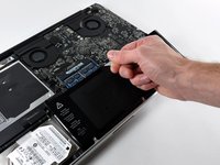
Remove the two 5-Point Pentalobe screws along the top edge of the battery.
Question: why do you remove the battery? According to Apple's official manual, this is not required (not for the mid-2009 and not for the mid-2010 15-inch MacBook Pro) - see pages 37 ff:
Citação de alexkli:
Question: why do you remove the battery? According to Apple's official manual, this is not required (not for the mid-2009 and not for the mid-2010 15-inch MacBook Pro) - see pages 37 ff:
I'm interested by your experience.
Did you have removed the optical drive without removing the battery ?
I'm just in this step now and if it is possible I would proceed like you because removing the battery void the warranty (and there is a sticker).
Thanks in advance.
Looks like my note to step 3 appears on all repair guides that have the same step. I meant that in the context of the hard drive replacement only.
Did you have removed the optical drive without removing the battery ?
I haven't yet done anything, waiting for my MacBook Pro 15 inch mid-2010 to arrive.
I missed the notes and went ahead and purchased the 5 point driver for the battery before I realized it was not necessary.
I've edited the repair guide to remove the section on the battery, but I don't have the points to approve the changes.
Please note - the step about removing the battery is part of a pre-requisite guide, that is used for many of the guides, most that do require removal of the battery. Also, working inside a disassembled laptop with the battery still connected risks damaging/shorting out very expensive parts.
Absolutely. To be clear -- ALL of the above discussion is ONLY in reference to replacing the hard drive.
I replaced a hard drive in a MacBook Pro of an earlier model than this without removing the battery. The hard drive wasn't right. It only worked at about half speed, and I had to replace it once more. The second time I removed the battery and all went well. The recommendation by the iFixit staff to remove the battery before working on electronic equipment is a good one.
What is the size of those screws... I have rounded off the socket on mine and would like to replace them.
I measured the screw size, using a micrometer, its about 1.523mm in diameter and 3.186mm in length. Not sure what screw size that is. They are not easily available I guess, unless someone is selling used ones on ebay
In my case the three pentalobe screws were 3 point.
-
-
-
Lift the battery by its plastic pull tab and slide it away from the long edge of the upper case.
My T6 (appears to be same screw driver you have - $6 on amazon for 20piece set) did NOT fit int he battery screws...not sure if I had the wrong screws or what, but I went ahead w/o battery steps and it was pretty easy.
I also noticed that the new SDD (from crucial) didn't have the 4 screws, so I had to move those off the old HD and onto the new one.
Just had the same issue: T6 does not fit the battery screws ;-( ... but with a little bit more preassure it was possible to remove the screws.
-
-
-
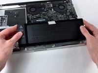
Tilt the battery back enough to access the battery cable connector.
-
Pull the battery cable connector away from its socket on the logic board and remove the battery from the upper case.
-
-
-
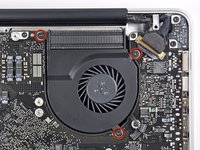
Remove the three T6 Torx screws securing the left fan to the logic board.
-
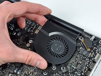
Lift the fan out of the upper case.
Top left screw in this picture isn't a torx screw, and should be left in place. The screw you want is a bit further down than the one circled.
Good catch! It's fixed now.
-
-
-
Use the flat end of a spudger to disconnect the left fan connector from the logic board.
I didn't understand the description of the step to remove the fan connectors and I broke them both off. However! If anyone else does this, don't panic, the soldered connections are not electrical; they're just there to secure the fan connector. If you have the equipment you may be able to solder them back on, but I just put the whole thing back together - carefully sliding the jack back over the pins - and held it down with polyimide tape. I am using my Macbook Pro right now and the fans are definitely working.
For my Mid 2009 Macbook Pro, I only had one fan, so didn't have to do step 9 and 10.
-
-
-
Remove the three T6 Torx screws securing the left fan to the logic board.
-
Lift the left fan out of the upper case.
For my Mid 2009 Macbook Pro, I only had one fan, so didn't have to do step 9 and 10.
-
-
-
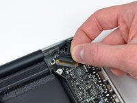
Hold the end of the cable retainer down with one finger while you use the tip of a spudger to slightly lift the other end and rotate it away from the camera cable connector.
-
Disconnect the camera cable by pulling the male end straight away from its socket.
I’ve tried to clear things up in a pending modification, since I also had problems getting the point of this step. Hope it helps.
The “strip” is the shiny black thing on the photo. The tip of the spudger is “pointing” at it on the photo. In fact it is already pushing the “strip” out of the way to be able to pull out the connector.
I finally got my system back together & running so much cooler after removing, cleaning the heat sink & repasting the CPU die & the two GPU dies. But working backward from this step to put it back together was most arduous: neither camera nor WiFi/Bluetooth worked when I first put the system back together. This is because it was hard to gauge that this connector was indeed back together and hold it so, based on 12 year-old fabric-padded adhesive alone. In the end, I checked that no pins in the connector were bent, guided them in as firmly as a flat spudger (not my hand, which twisted the cable at an angle) would allow, held it in the connector bay with electrical tape, put the fabric cushion back on top of that, and electrical taped across the cushion, between the connector bay and the cable. Phew! After tons of trial and error, put the system back together & both WiFi/Bluetooth and the camera work again!
-
-
-
-
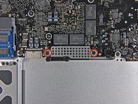
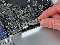
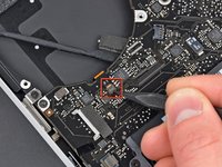
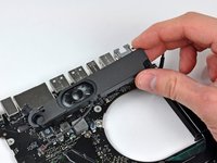
Using the flat end of a spudger, pry the subwoofer connector straight up from the connector jack.
-
-
-
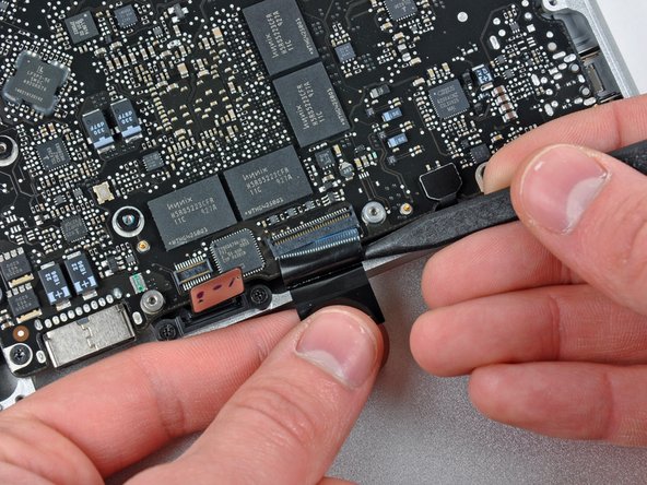
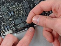
Use your fingernail to flip up the locking flap on the ZIF socket for the keyboard ribbon cable. The locking flap is located at the opposite side of the socket compared to the keyboard ribbon cable. Hook your fingernail under it and carefully lift it up vertically.
-
Use the tip of a spudger to slide the keyboard ribbon cable out of its socket.
-
-
-
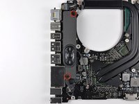
Remove the following screws:
-
Seven 3.3 mm T6 Torx screws securing the logic board to the upper case.
-
Two 8 mm T6 Torx screws securing the DC-In board to the upper case.
-
-
-
-
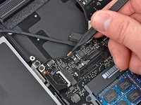
Use the flat end of a spudger to pry the microphone cable connector up off its socket on the logic board.
-
-
-
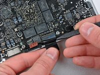
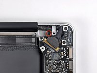
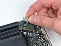
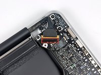
Disconnect the DC-In Board connector from the logic board by pulling it straight away from its socket.
-
-
-
Carefully lift the heat sink off the logic board.
What if I only want to put some thermal paste on the processors? Do I have to dismantle the hole computer? By the way where are the processors in this picture? Thank you so much !!!!!!
-


To reassemble your device, follow these instructions in reverse order.
To reassemble your device, follow these instructions in reverse order.
Cancelar: não concluí este guia.
39 outras pessoas executaram este guia.

May be helpful to have more distinct colors to identify the different screws.
Victor Caamano - Responder