Introdução
Use this guide to replace the trackpad in a 2018 MacBook Air.
O que você precisa
-
-
If your MacBook is running Big Sur v11.1 or later, disabling Auto Boot may not work. You can proceed normally, but make sure to disconnect the battery as soon as you're inside.
-
Use a P5 driver to remove the following screws:
-
Two 7.9 mm screws
-
Two 7.1 mm screws
-
Six 2.6 mm screws
-
-
-
Wedge your fingers between the display and the lower case and pull upward to pop the lower case off the Air.
-
Remove the lower case.
Are there any suggestions to removing the pressure fasteners more easily?
I used a suction cup to lift up the cover. I mean those to lift up an iPhone display. Worked like charm.
-
-
-
Peel back the tape covering the battery connector enough to reveal the connector underneath.
-
-
-
Use a spudger to slide the battery connector parallel to the logic board and out of its socket on the logic board.
Before the battery can be fully disconnected, the battery disconnect button needs to be held down. There is a gold button just above the battery socket, along with a small LED much like the 12” machines. Once this has been held down and the LED has switched off it is safe to remove the battery.
This seems like an important step?
Also, seems like this should be done after the battery is disconnected, not before? Otherwise, wouldn’t the battery re-charge it?
What if the white LED dosent light up after pressing the yellow button again?
Iron05 -
I just performed this repair on my late 2018 mac air. I did click the gold button but saw no LED illuminated or otherwise. Question- after reassembly does the button get pressed again to connect the battery? Please clarify if this button is to be pressed and if it needs pressing again after the repair.
All said - I pressed again after the battery connector clicked, assembled the back and all worked perfectly. The original issue was one dead port (no charge, no communication). The battery charge lightening bold icon was acting funny too. Genuis bar guy in Naperville said it was likely a logic board too. But it was not. The port was apparently confusing the logic board with regards to the charge function. Thanks Adam for saving me $440 and sending my computer back to Apple. I am 71 yrs young - who says an old dog can’t learn new tricks with good training!!
I didn't see Aaron's comment before completing the battery replacement. Afterwards, the computer would not turn on despite multiple SMC reset procedures. Upon double-checking the comments I see the importance of pressing the gold button. I pressed the gold button before disconnecting the new battery, then pressed it again after reconnecting for good measure. Computer booted!
It would be good of iFixit to add this important step as most people probably don't open up every single comment on (seemingly) simple steps.
Seconding Corey's comment. If paid more attention to the comment section, I would have avoided 15-30 minutes of panic. (BTW I did not notice any LED, but the golden button was easy to find).
Where is the gold button? I replaced my battery and my laptop will not start
-
-
-
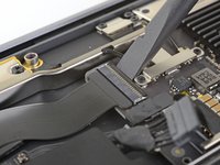
Use a T3 Torx driver to remove the two 1.4 mm screws securing the trackpad connector bracket.
-
Remove the trackpad connector bracket.
My machine used T4 screws
Me too! I tried with T3 and it wasn’t working.
I stripped my screws trying to get them out with a t3 driver...
-
-
-
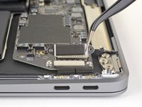
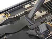
Slide the tip of a spudger underneath the left speaker cable and pry straight up to disconnect the speaker.
-
With the connector disconnected, slide the flat end of a spudger under the cable to separate the adhesive securing the cable to the logic board.
-
-
-
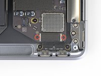
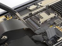
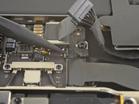
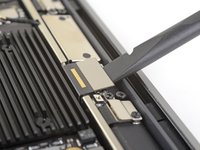
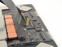
Use a T3 Torx driver to remove the two 1.3 mm screws securing the USB-C port connector bracket.
-
Remove the USB-C connector bracket.
There is no need to remove the logic board!!
Skip steps 16 through 28 and go to step 29 to release the trackpad cable from the battery. then follow steps to 30 through 33 to release the battery. The battery can be removed by slipping it counter-clockwise under the trackpad cable. The new battery can be slipped in place in the same way.
Much easier!!
Removing a few of the logic board screws allowed me to get the to right screw bracket under the logic board to give enough clearance as w98fxr mentioned.
This can be done, but it's very tight. Still, beats removing the logic board and the possibilities of breaking something in the process.
-
-
-
-
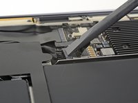
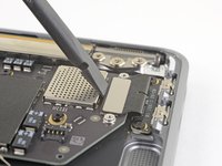
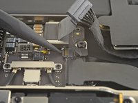
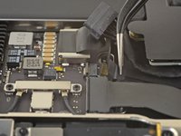
Use the flat end of a spudger to pry the USB-C cable connector up and out of its socket on the logic board.
please reconsider removing the logic board and and usb-c connector as is recommended in the prior step. i had a very difficult time reconnecting the usb-c connector
It should be cautioned that this connector is very easily bent, meaning a bend in the length of the metal surface you press against to reconnect (or pry against for removal). Once bent it becomes very hard to establish a good connection.
-
-
-
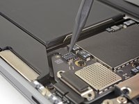
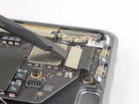
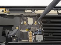
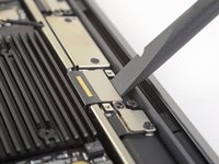
Use a spudger to lift up the small locking flap on the sound board cable's ZIF connector.
-
Slide the sound board cable out of the ZIF connector.
-
-
-
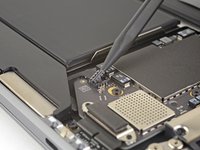
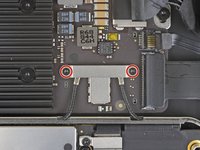
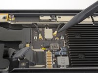
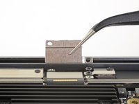
Use a T3 Torx driver to remove the two 1.4 mm screws securing the antenna cable bracket.
-
Remove the antenna cable bracket.
These are T4 screws
The MBA I just finished with were T3. I'm fairly confident with my tools as I recently updated/upgraded nearly my entire set with WiHa. I should also mention the many tools acquired from iFixit over the years have all been were exceptional lasting years. There's no doubt iFixit would have been my source but a close friend went to work for WiHa. His discount(s) & being motivated to help him was a major impact. For anyone not having such an advantage IMHO tools from iFixit are one of the best values anywhere. Let's not forget; buying from iFixit will also help to push "Right to Repair" forward. Here in Minnesota Right to repair ALMOST PASSED. Many believe it will become law during the next session! I can't tell you how proud this would make me. I would obtain as many service manuals as possible and post them all online!!! What a great dream...
-
-
-
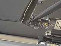
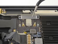
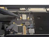
Insert the point of a spudger under one of the antenna cables close to the connector. Pry straight up to disconnect the cable.
-
Repeat for the other antenna cable.
Be SUPER SUPER CAREFUL pulling off the gold WiFi antenna connectors! As described, use the spludger to press up the black cable just behind the metal connector. I tried to ping them off from the bottom of the gold connector where it clips into the socket on the motherboard and ended up pulling off the SMD sockets from the motherboard - huge and costly mistake that will probably render it useless.
-
-
-
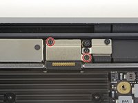
Use the flat end of a spudger to pry up the display cable connector.
How do I reconnect display connector??
Just align the plug section of the display flex with the socket on the logic board and gently press it in until it locks in place. Do not force it but just ensure it’s correctly aligned before pushing it into the socket.
Pro tip: You can remove the two T5 screws on the LCD connector side (located to the right of the display connector and to the left of the heat shield). From there, tilt the whole skinny LCD board towards the logic board connector and gently pinch the connector in to the socket. Before laying the skinny board back down, screw in the shield from Step 15 so it doesn’t pop out of the socket again.
-
-
-
Use a T5 Torx driver to remove the following screws:
-
One 5.5 mm screw
-
Three 2.6 mm screws
-
Two 1.9 mm screws
These are T5 Torx driver screws
Need torx 5 AND torx 4 driver here ;)
During re-assembly be soft when screwing in the logic board because those antenna plugs in Step 14 are quite awkward to pin back into their sockets and there is little leeway in the cables; to make this task a little easier in Step 14, secure the logic board loosely right up against the near outside edge; after re-connecting all the cables in Steps 16-9, return to Step 17 to firm up the logic board screws.
This tip was a huge help, hate these cables lol
The 5.5 mm screw goes into a hexagon standoff which may come off with the logic board being sanswiched beteen the 5.5 mm screw screw and the standoff like happened to me. Just something to be aware of. It also has a black rubber bumper over the screw which was not mentioned at all. It pulls straight off to give access to the screw.
On my board I needed to use T6 for all the screws except the rubber bumper for which I used a T7. I have a full set of small Torx drivers and tried for the best fit.
T5 fit best is all the screws on my machine
-
-
-
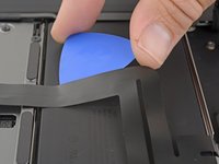
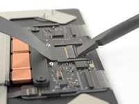
Carefully slide an opening pick under the trackpad cable towards the keyboard connector to separate the adhesive securing it to the upper case.
-
-
-
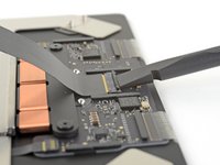
Use the flat end of a spudger to lift the small locking flap on the keyboard ZIF connector.
-
Slide the keyboard cable straight out of its connector.
-
-
-
Carefully slide an opening pick under the trackpad cable to separate the adhesive securing it to the battery.
-
-
-
Use a T5 Torx driver to remove the following screws securing the trackpad:
-
One 3.2 mm screw
-
Eight 3.1 mm screws
-
-
-
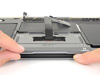
With the laptop still lying screen-side down, carefully open the laptop. The trackpad will stay sitting on the display.
-
Remove the trackpad from the MacBook. Take care not to scratch the display.
-
-
-
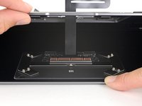
Use the flat end of a spudger to lift the small locking flap on the trackpad's ZIF connector.
-
Slide the trackpad cable straight out of the ZIF connector.
-


Compare your new replacement part to the original part—you may need to transfer remaining components or remove adhesive backings from the new part before installing.
To reassemble your device, follow the above steps in reverse order.
Take your e-waste to an R2 or e-Stewards certified recycler.
Repair didn’t go as planned? Check out our Answers community for troubleshooting help.
Cancelar: não concluí este guia.
3 outras pessoas executaram este guia.

Um comentário
nice guide - Just one thing that needs to be added is that there are 5 small metal retaining washers (4 x double and one single) on the underside of the trackpad unit, which can just be seen in the 2nd picture in STEP 23 that need to be carefully removed and put back in place on the replacement unit. If these are NOT moved to the new unit, it will not sit properly.
If the first thing you do is disconnect the battery, is it really an issue if you don’t (or can’t) disable auto-boot?
maccentric - Responder
I agree, why disable Auto-Boot when the lid is closed and the battery is disconnected immediately? – I've never had an issue since 2016 when the feature was introduced.
stevebsiegel - Responder
On my machine, the longest two screws were in the corners, while the other two long screws were in the middle. Perhaps previous service in the past had them replaced into the wrong place? In any case, the longest screws do seem to fit in either place. I guess 0.8mm is not very much of a difference. Seems like poor design if they could have used one size of screw.
johann beda - Responder
Just did one, and it also had longest screws in the corners.
maccentric -
Just did another, and the long ones were in the middle. Definitely poor design and quality control.
maccentric -