Introdução
This repair guide was authored by the iFixit staff and hasn’t been endorsed by Google. Learn more about our repair guides here.
Use this guide to replace the screen assembly in your Google Pixel 3.
This guide is written for the genuine Google screen assembly. The assembly consists of the screen and frame together in one part. Be sure you have the right part before you begin the repair.
Some photos in this guide are from a different model and may contain slight visual discrepancies, but they won't affect the guide procedure.
O que você precisa
-
-
Insert a SIM eject tool, bit, or straightened paper clip into the SIM card tray hole.
-
Press the SIM eject tool into the SIM card tray hole to eject the SIM card tray.
-
Remove the SIM card tray.
-
-
-
Heat an iOpener and apply it to the bottom of the phone for one minute.
-
-
-
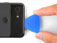
Apply a suction cup to the heated bottom edge of the back cover.
-
Lift on the suction cup with strong, steady force to create a gap.
-
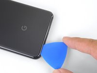
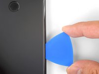
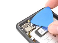
Insert an opening pick into the gap.
-
-
-
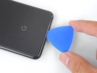
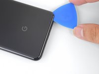
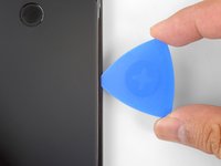
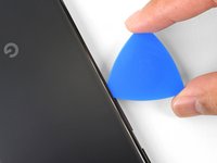
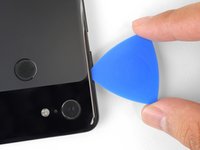
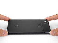
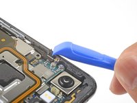
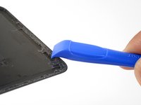
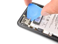
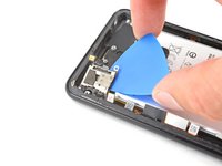
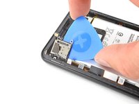
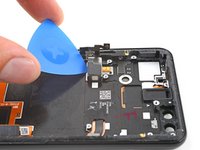
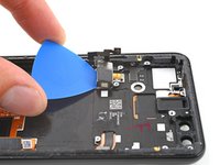
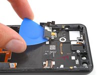
Slice the adhesive along the bottom edge of the phone and around the right corner.
-
Leave a pick in the bottom edge to prevent the adhesive from re-sealing.
-
-
-
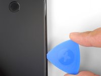
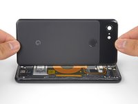
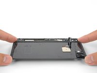
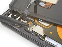
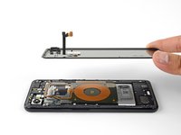
Once you have sliced around the perimeter of the phone, carefully lift the left edge of the back cover.
-
Flip the back cover along its long axis and rest it so that the fingerprint sensor cable is not strained.
-
-
Ferramenta utilizada neste passo:Magnetic Project Mat$19.95
-
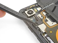
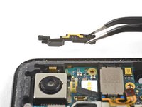
Remove the two 4.1 mm-long Phillips screws securing the fingerprint connector bracket.
-
-
-
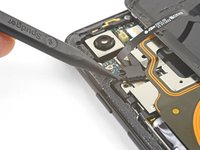
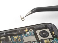
Use the point of a spudger to slide the fingerprint connector bracket out from under the NFC coil.
-
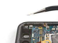
Remove the fingerprint connector bracket.
-
-
-
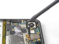
Use the point of a spudger to pry up and disconnect the fingerprint connector from its socket.
-
-
-
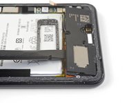
Remove the five Phillips screws securing the wireless charging coil:
-
Two 1.9 mm screws
-
Two 4.2 mm screws
-
One 4.3 mm screw
-
-
-
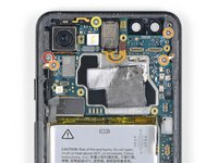
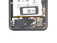
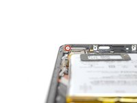
Use the point of a spudger to pry up and disconnect the battery press connector from its socket near the right edge of the phone.
-
-
-
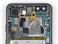
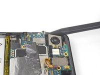
Remove the two screws securing the camera bracket:
-
One 4.1 mm Phillips screw
-
One 4 mm standoff screw
-
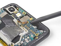
Remove the camera bracket.
-
-
-
Use the point of a spudger to pry up and disconnect the connector for the camera(s) you are replacing.
-
-
-
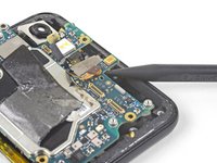
Insert the point of a spudger behind the edge of the camera module and pry up to loosen it from the frame.
-
-
Ferramenta utilizada neste passo:Tesa 61395 Tape$5.99
-
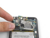
Use a pair of blunt nose tweezers to remove the camera(s).
-
-
-
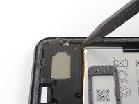
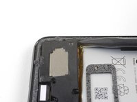
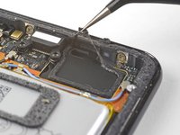
Use the point of a spudger to pry up and disconnect the loudspeaker connector from its motherboard socket near the right edge of the phone.
-
-
-
-
Remove the following four Phillips screws:
-
One 1.9 mm screw
-
One 4.3 mm screw
-
Two 4.3 mm screws with thinner shanks
-
Remove the tiny grounding clip from the left screw hole. Be careful not to lose it.
-
Remove the small plastic insert from the right side of the USB-C port.
-
-
-
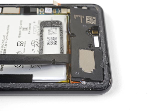
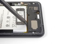
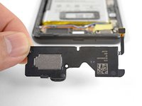
Insert the point of a spudger under the bottom right corner of the loudspeaker.
-
Pry up to loosen the loudspeaker from the phone.
-
-
-
Remove the loudspeaker.
-
If it is in good condition, you can re-use the gasket. Make sure that the gasket does not cover the exit hole.
-
If the gasket is pulled out of place, remove it and replace the adhesive with a pre-cut strip or Tesa tape.
-
-
-
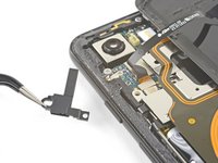
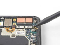
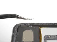
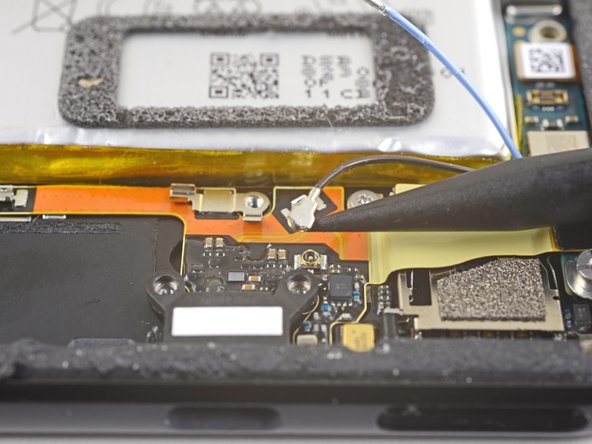
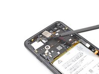
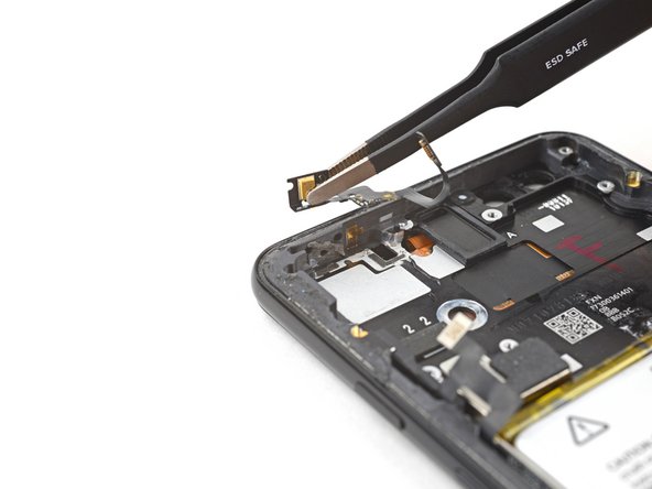
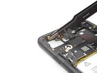
Use the point of a spudger to pry up and disconnect the blue antenna cable from its socket on the charging assembly.
-
-
-
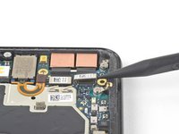
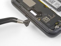
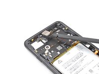
Use the point of a spudger to pry up and disconnect the black antenna cable from its socket near the USB-C port.
-
-
-
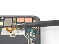
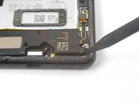
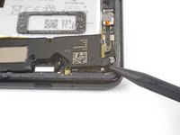
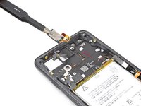
Carefully de-route both antenna cables and move them away from the charging assembly.
-
-
-
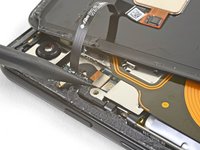
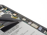
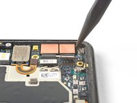
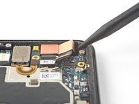
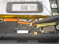
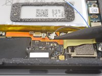
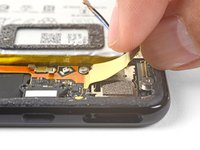
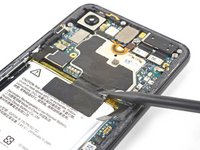
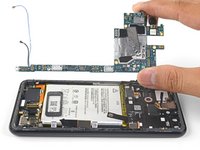
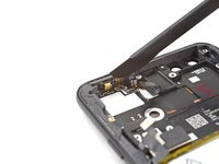
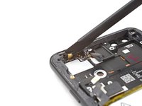
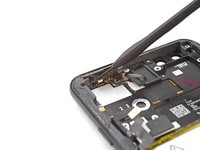
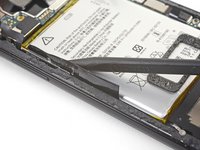
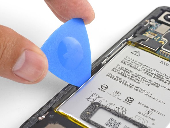
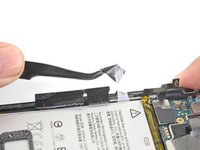
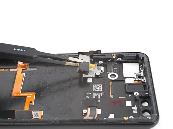
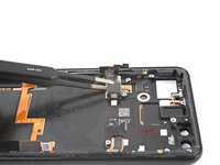
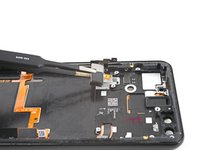
Use the flat end of a spudger to carefully pry up the black tape holding the display flex cable in place, near the right edge of the phone.
-
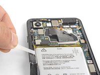
Use the flat end of a spudger to pry up and disconnect the display connector from the motherboard.
-
-
-
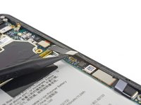
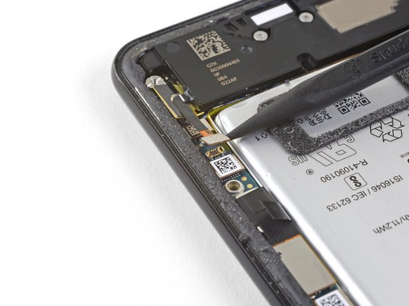
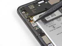
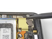
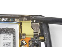
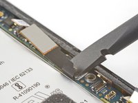
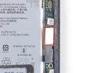
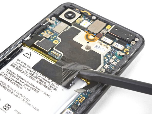
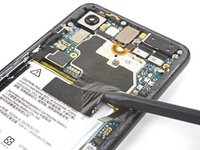
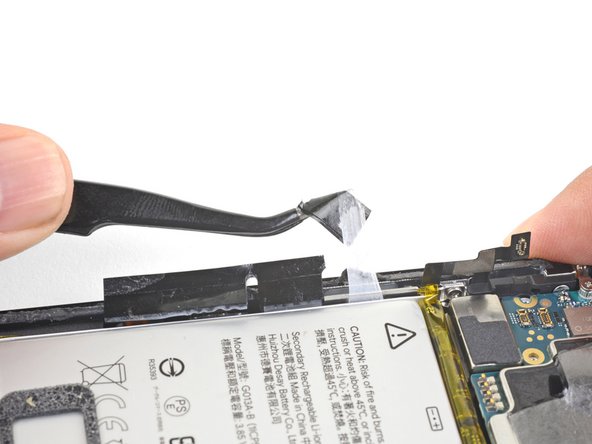
Slide the point of a spudger in the crevice underneath the black tape bridging across the battery and the motherboard.
-
Slide the spudger along the crevice to pry up the tape from the battery side.
-
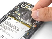
Carefully peel the tape from the battery and fold it out of the way.
-
-
-
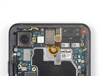
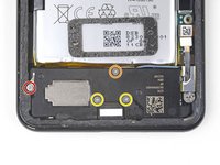
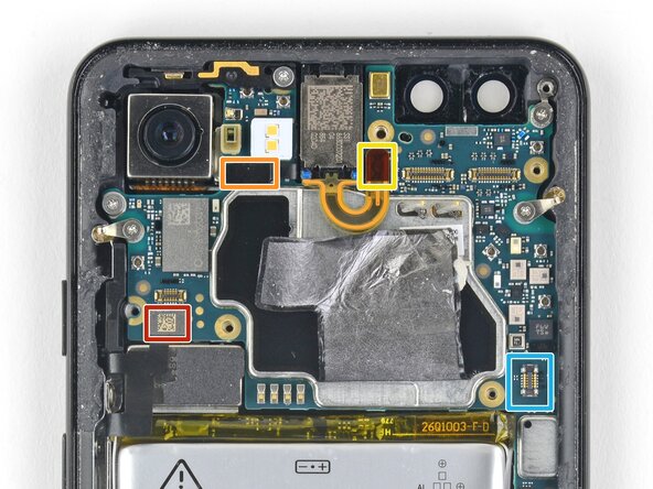
Use a spudger to pry up and disconnect the following seven press-fit connectors from their motherboard sockets:
-
External buttons connector
-
Top microphone connector
-
Earpiece connector
-
Left squeeze sensor connector
-
Touchscreen (first picture) and OLED display (second picture) connectors
-
Right squeeze sensor connector
-
SIM tray connector
-
-
-
Use the flat of a spudger to carefully pry up and bend the earpiece speaker's flex cable upwards, out of the way of the motherboard.
-
-
-
Remove the six screws securing the motherboard in place:
-
One 4.2 mm Phillips screw
-
Three 1.9 mm Phillips screws
-
One 4.3 mm Phillips screw
-
One 3.83 mm standoff screw
-
Remove and retain the three small metal grounding clips.
-
-
-
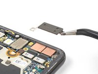
Carefully remove the antenna bracket from the top left edge of the phone.
-
Orient the clips such that the silver side is facing upwards.
-
The teardrop shaped clips should have their points facing towards the phone edge.
-
The double-holed clip dips downwards towards the frame's top-right screw hole.
-
-
-
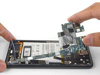
Insert the point of a spudger near the top left corner of the motherboard, right below the rear-facing camera.
-
Pry up gently to loosen the motherboard, bending all flex cables away to accommodate for the movement.
-
If the motherboard feels firmly seated, check for any flex cables or screws that may still be connected.
-
-
-
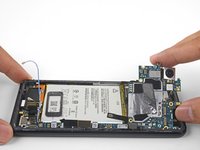
Insert the spudger underneath the top edge of the motherboard and carefully pry up to loosen the motherboard.
-
-
-
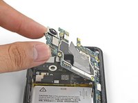
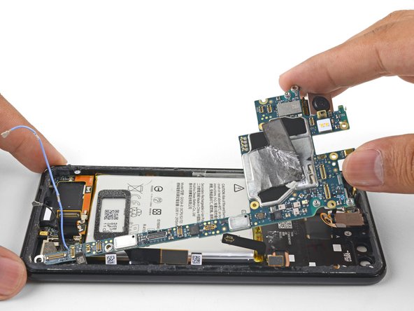
Lift the left edge of the motherboard and carefully swing it upwards towards the right. Carefully push any press connectors snagging the motherboard out of the way.
-
-
-
Carefully lift the top end of the motherboard away from the frame.
-
Remove the motherboard.
-
-
-
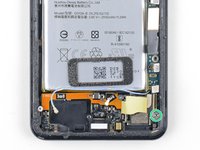
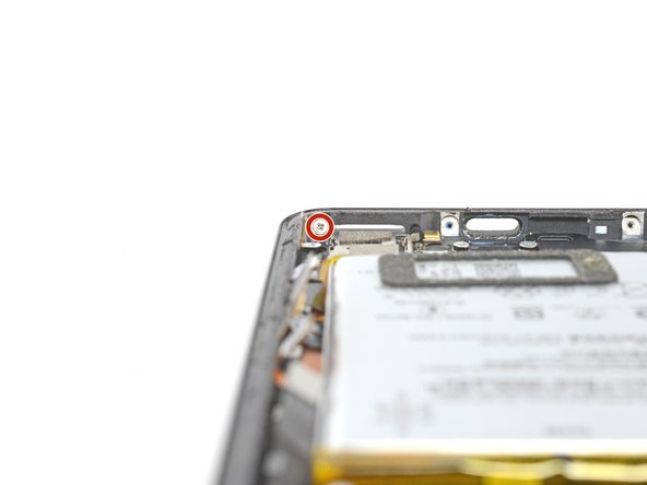
Remove the two 1.9 mm Phillips screws securing the charging assembly to the bottom edge of the phone.
-
-
-
Apply a heated iOpener to the bottom edge of the phone for a minute to loosen the adhesive holding the charging assembly in place.
-
-
-
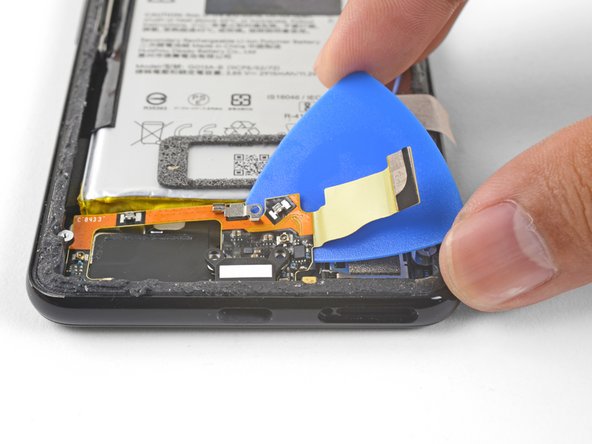
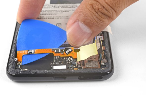
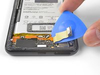
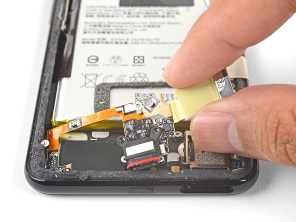
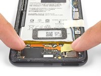
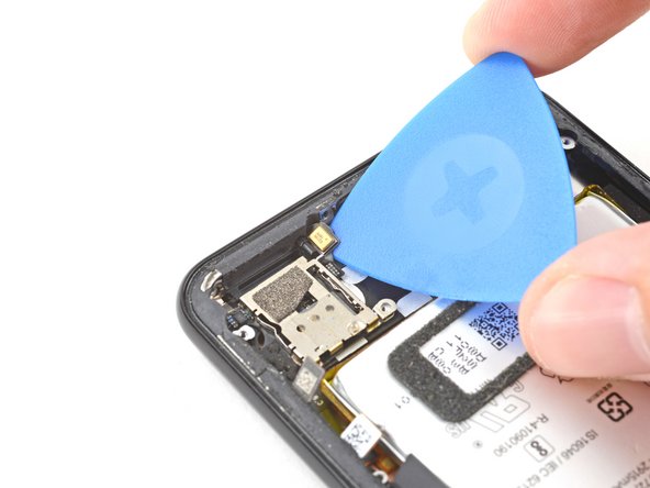
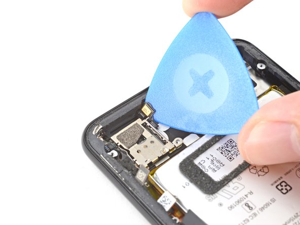
Insert an opening pick underneath the charging assembly's flex cable.
-
Slide the opening pick below the charging assembly to loosen it from the phone.
-
-
Ferramenta utilizada neste passo:Tweezers$4.99
-
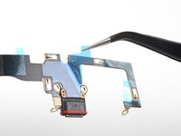
Use a pair of tweezers or your fingers to remove the charging assembly.
-
-
-
Be sure to remove all plastic liners from the assembly to expose the adhesive.
-
Line up the assembly's bottom left corner into place.
-
Carefully lay the rest of the assembly in place, making sure that the USB-C port is correctly seated in its respective cutout.
-
Use your fingers to press the assembly onto the frame.
-
-
-
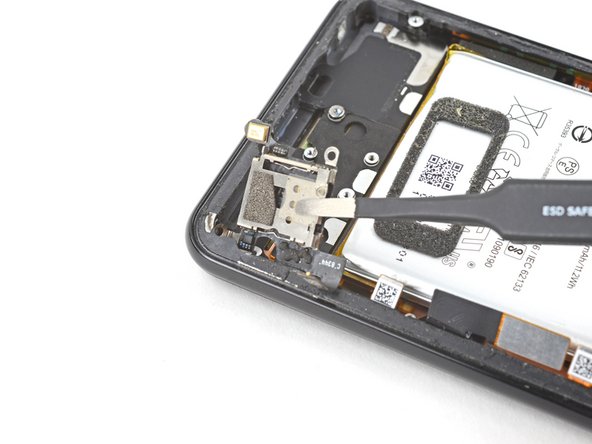
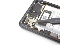
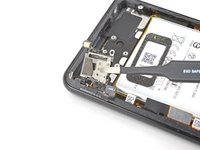
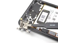
Use a Phillips screwdriver to remove the two 1.9 mm screws securing the SIM card reader.
-
-
-
Heat an iOpener and apply it to the bottom right of the device for two minutes.
-
-
-
Insert an opening pick between the frame and the lower microphone module.
-
Pry up with the opening pick to separate the adhesive.
-
-
Ferramenta utilizada neste passo:Tweezers$4.99
-
Use tweezers, or your fingers, to lift up the SIM card reader and separate the remaining adhesive.
-
Remove the SIM card reader.
-
-
-
Heat an iOpener and apply it to the top edge of the device for two minutes.
-
-
-
Insert the flat end of spudger between the earpiece speaker and the frame.
-
Pry up with the spudger to separate the adhesive.
-
Remove the earpiece speaker.
-
-
-
Heat an iOpener and apply it to the top left of the device for two minutes.
-
-
Ferramenta utilizada neste passo:Halberd Spudger$2.99
-
Insert a halberd spudger or an opening pick between the microphone assembly and the perimeter of the frame.
-
Slide the halberd spudger downward and pry towards the battery to separate the adhesive.
-
-
-
Use tweezers, or your fingers, to remove the microphone assembly.
-
-
-
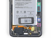
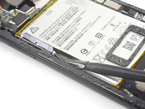
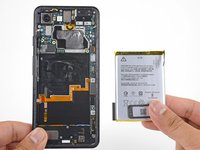
Insert the point of a spudger underneath the black battery pull tab on the left edge of the phone.
-
Slide the spudger upwards along the edge to loosen the pull tab from the battery.
-
-
-
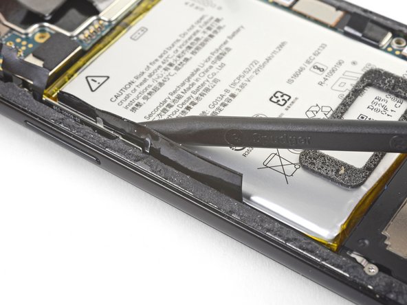
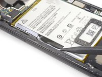
Pull on the black pull tab at a shallow angle with steady force. When the adhesive grows long, roll it around some tweezer tips and continue pulling.
-
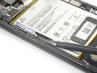
If the adhesive strips break, use an opening pick to help pry up and loosen the battery.
-
-
-
Remove the battery.
-
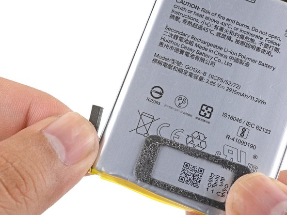
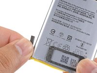
Carefully pull and remove the small foam buffer block from the left edge of the battery and transfer it to your replacement part. If it begins to tear, use the flat end of a spudger to gently pry it off the battery.
-
Lay some double-sided tape in the phone's battery well. If you're using Tesa tape to reattach components, follow this guide. If using stretch-release adhesive, follow this guide.
-
Temporarily re-connect the battery's connector to the motherboard socket. This ensures that the battery is properly positioned.
-
Peel away any tape liners to expose the adhesive.
-
Lay the battery on the adhesive and press firmly.
-
Disconnect the battery connector from its motherboard socket and resume re-assembly.
-
-
-
Insert an opening pick between the frame and the long edge of the vibrator.
-
Slide the pick underneath the vibrator to separate the adhesive.
-


Compare your new replacement part to the original part—you may need to transfer remaining components or remove adhesive backings from the new part before you install it.
To reassemble your device, follow these instructions in reverse order.
Take your e-waste to an R2 or e-Stewards certified recycler.
Repair didn’t go as planned? Check out our Google Pixel 3 Answers community for troubleshooting help.
Cancelar: não concluí este guia.
5 outras pessoas executaram este guia.


4Comentários do guia
Very helpful guide overall. My first time trying a repair like this and it went well. Took me about 5 hours in total from start to finish. Took the longest to open the phone up in the first place, and then to align the motherboard during reassembly. Thank you for this guide!
Fantastic guide! Took me a little over 4 hours. I did break the earpiece ribbon cable, though. I bent it up and down twice since I had to backtrack and fix a mistake, and the repeated movement must have stressed it.
Very helpful overall, but "1-2 hours" is off by a factor of at least two. In Step 36 I also hit a snag when encountering smooth-topped circuit board offsets, in place of the 1.9 mm Phillips screws that were advertised here. I bought the iFixit screw removal pliers to remove them but was unable to put them back... I'm told that if I knew the thread size, I could replace them with others that have a hex-shaped body (and then use a hex driver to install), but in the meantime I'm willing to live with a loose motherboard.
Solid guide, though I wonder why some of the order differs from the others Pixel 3 guides, especially with the battery. Why not take it out immediately? Trickiest part is the initial opening - take your time, multiple iOpener passes, and come at the seam at an angle with the pick - and the earpiece-motherboard situation - the earpiece is stuck on with a strong adhesive, so trying to pry it up prior to removing the motherboard can be disastrous (for the earpiece). I found the magnetic project mat that iFixIt sells to be very helpful. Make sure to get a new speaker gasket as well, and new battery adhesive, or use Tesa tape. The standoff driver was bonus, but far from necessary. Also! Get some of the graphite sheeting that iFixIt sells for the Pixel 6, 7, or 8 to replace the stuff you inevitably tear through when removing the battery. Just cut it to size, pretty sure it's the same (or similar but upgraded) stuff. Good luck! Definitely block out a solid four or five hours for this - reduce time pressures!