Esta versão pode conter edições incorretas. Mude para o último instantâneo verificado.
O que você precisa
-
-
Desligue o seu iPhone antes de começar a desmontagem.
-
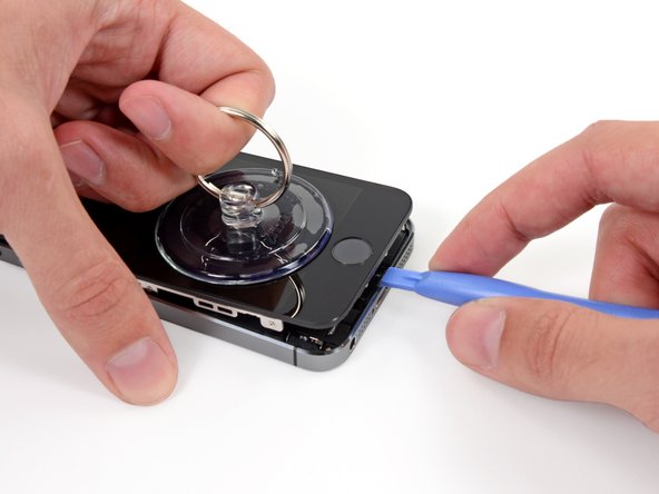
Remova os dois parafusos pentalobe de 3,9 mm de ambos os lados do conector Lightning.
-
-
-
Se o vidro de seu visor estiver rachado, mantenha as rachaduras sob controle e evite danos corporais durante o reparo cobrindo o vidro com fita adesiva.
-
Coloque tiras sobrepostas de fita adesiva transparente sobre a tela do iPhone até que toda a superfície fique coberta.
-
-
-
Independente da ferramenta que você use, você precisa puxar para cima com segurança o visor inteiro.
-
Se o vidro começar a se separar do plástico, como mostra a primeira figura, passe uma ferramenta de abertura de plástico por entre a moldura de plástico e o corpo metálico do fone para liberar os clipes metálicos da estrutura.
-
-
-
Puxe a pega azul para trás para destravar os braços do Anti-Clamp.
-
Deslize os braços pela borda esquerda ou direita do seu iPhone.
-
Posicione as ventosas próximo à borda inferior do iPhone, diretamente acima do botão home - uma pela dianteira e a outra pela traseira.
-
Aperte as ventosas uma contra a outra para aplicar sucção na área desejada.
-
-
-
Se você não tiver um Anti-Clamp, use uma ventosa de sucção simples para erguer o painel dianteiro:
-
Pressione uma ventosa de sucção sobre a tela, imediatamente acima do botão home.
-
-
-
Enquanto segura o iPhone com uma mão, puxe para cima pela ventosa de sucção para separar ligeiramente a extremidade com o botão home do painel dianteiro da estrutura traseira.
-
Com uma ferramenta de abertura de plástico, comece a fazer alavanca para baixo nas bordas da estrutura traseira, afastando-as do conjunto do painel dianteiro, enquanto puxa para cima com a ventosa de sucção.
-
-
-
Abra o fone apenas o bastante para revelar o suporte metálico que cobre o cabo do botão home.
-
Somente o conjunto do botão home original poderá permitir o uso da funcionalidade da identificação por toque. Se você romper o cabo, a instalação de um novo botão home apenas restaurará as funções normais do botão home, mas não os recursos de identificação por toque.
-
Com a ponta pontiaguda de uma espátula, empurre o suporte, liberando-o e remova-o com uma pinça.
-
-
-
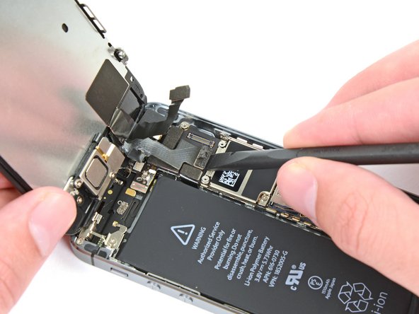
Use a ponta pontiaguda de uma espátula para fazer alavanca e separar o conector do cabo do botão home de seu soquete.
-
-
-
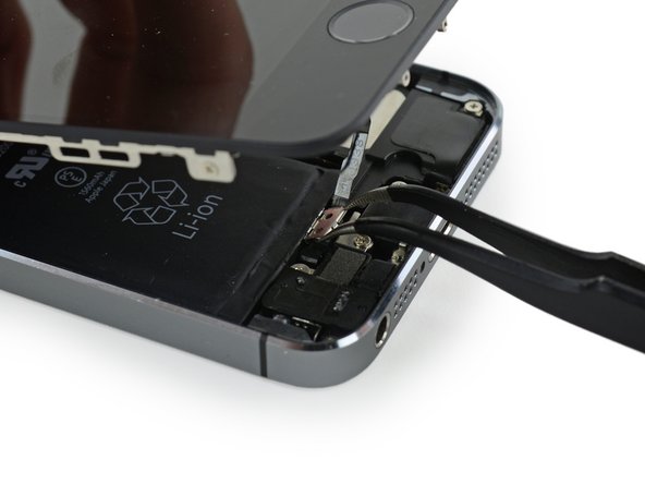
Uma vez solto o conector, puxe a ponta com o botão home do conjunto, afastando-o da estrutura traseira, usando a parte superior do fone como uma dobradiça.
-
Abra o visor a um ângulo de 90º e apoie-o em algo para deixá-lo de pé enquanto você executa os trabalhos no fone.
-
Engate uma fita de borracha para manter o visor no lugar com segurança enquanto executa os trabalhos. Isso evita que os cabos do visor sejam submetidos a uma tensão imprópria.
-
-
-
Este passo não foi traduzido. Ajude a traduzi-lo
-
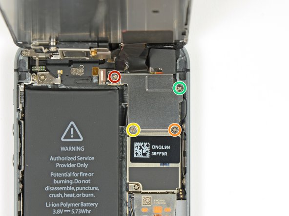
Remove the two screws securing the upper component bracket:
-
4.0 mm Phillips #000
-
2.3 mm Phillips #000
-
-
Este passo não foi traduzido. Ajude a traduzi-lo
-
Gently dislodge the clip, near the bottom left corner of the earpiece speaker bracket, outwards from its recess on the front panel assembly.
-
With a set of tweezers, shift the bracket to the left to unclip it.
-
-
Este passo não foi traduzido. Ajude a traduzi-lo
-
Remove the earpiece speaker with a set of tweezers.
-
-
Este passo não foi traduzido. Ajude a traduzi-lo
-
Place the earpiece speaker bracket over the speaker so that it fits snugly in its housing.
-
Slide the left hook of the bracket into the notch above the top left corner of the front facing camera.
-
Rotate the bracket so it lays flat on the rear case, aligning the two screw holes. Press the bracket into place, ensuring the hook on the right side of the metal bracket latches onto the display.
-
-
Este passo não foi traduzido. Ajude a traduzi-lo
-
Using an iOpener to soften the adhesive will help safely remove it. Follow our iOpener instructions to use it.
-
-
Este passo não foi traduzido. Ajude a traduzi-lo
-
Using the edge of a set of tweezers or a metal spudger, gently pry the earpiece speaker contact cable up, to separate this portion of the camera and sensor cable from the adhesive below.
-
-
Este passo não foi traduzido. Ajude a traduzi-lo
-
Use the point of a spudger to lift the ambient light sensor and proximity sensor out of their recess in the display assembly.
-
-
Este passo não foi traduzido. Ajude a traduzi-lo
-
Use the flat end of a spudger to gently peel the front-facing camera portion of the cable away from the display assembly.
-
-
Este passo não foi traduzido. Ajude a traduzi-lo
-
Carefully peel the cable assembly off of the LCD shield plate to remove it from the display.
-
-
Este passo não foi traduzido. Ajude a traduzi-lo
-
Unscrew the single captive Phillips #000 screw securing the home button cable.
-
-
Este passo não foi traduzido. Ajude a traduzi-lo
-
Fold the home button cable down, out of the way of the home button bracket.
-
-
Este passo não foi traduzido. Ajude a traduzi-lo
-
Remove the two 1.4 mm Phillips #000 screws from the home button bracket.
-
-
Este passo não foi traduzido. Ajude a traduzi-lo
-
Remove the home button bracket from the display assembly.
-
-
Este passo não foi traduzido. Ajude a traduzi-lo
-
Wedge the the tip of a spudger underneath the home button cable assembly.
-
Gently work the spudger underneath the cable to separate the home button cable from the front panel assembly.
-
-
Este passo não foi traduzido. Ajude a traduzi-lo
-
Gently push the top left corner of the home button up away from the front panel.
-
-
Este passo não foi traduzido. Ajude a traduzi-lo
-
Peel the home button the rest of the way off of the display by prying gently with a spudger.
-
-
Este passo não foi traduzido. Ajude a traduzi-lo
-
Remove the home button assembly from the front panel.
-
-
Este passo não foi traduzido. Ajude a traduzi-lo
-
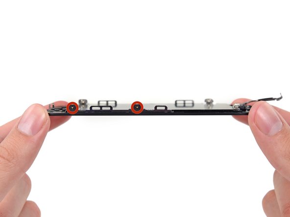
Remove the 2.7 mm Phillips #000 screw from the back of the display assembly.
-
-
Este passo não foi traduzido. Ajude a traduzi-lo
-
Remove two 1.2 mm Phillips screws from each side of the LCD frame (four total).
-
-
Este passo não foi traduzido. Ajude a traduzi-lo
-
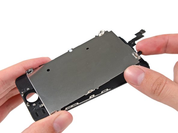
Remove the LCD shield plate from the display assembly.
-
The LCD and digitizer remains.
-


Cancelar: não concluí este guia.
120 outras pessoas executaram este guia.


7 comentários
Have issues after a couple days. I replaced the screen according to instructions and started up well. Screen started having issues and within a few minutes screen showed likes and faded to black.
This will be the screen that you have purchased, or due to a faulty repair…Not due to the guide.
Hi, thanks in advance for your support! I managed to detach the digitizer from the LCD after a small drop, thus I bought a replacement screen from ifixit… unfortunately resulting in a very bad quality aftermarket piece. Dimmed luminosity, changes in temperature(color), and affected by polarized glass, which I wear. I already reclaimed this to Ifixit and I`m waiting for support, but I thought to pick up my broken original display and glue back the digitizer, is that possible, or is this shown in any guide here around??
Thanks again!
STEPS 9-12 need a re-working - Re-assembly instructions should be put just under the disassembly instructions so that when you scroll back up the page, you’re re-assembling in step order ;)