Introdução
Use this guide to replace a broken home button.
O que você precisa
-
-
Power off your iPhone before beginning disassembly.
-
Your phone's rear cover may have two #000 Phillips screws or Apple's 5-Point "Pentalobe" screws. Check which screws you have, and ensure you also have the correct screwdriver in order to remove them.
-
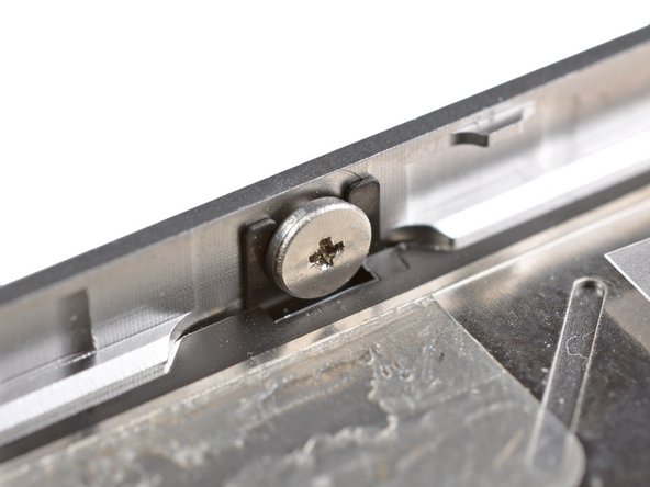
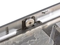
Remove the two 3.6 mm Pentalobe or Phillips #000 screws next to the dock connector.
-
-
-
Push the rear panel toward the top edge of the iPhone.
-
-
-
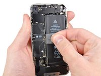
Remove the single 1.5 mm Phillips screw securing the battery connector to the logic board (if present).
you do not need to take the battery out as chuck said so you dont run the risk of braking the battery connector socket from the logic board
Won't you need the battery removed to access the large-headed screws on the side which hold the front display?
Unfortunately the battery screw was already stripped probably from original assembly. We used a pair of nail clippers as pliers to grab a hold of the screw by the edges to turn it. If it hadn't have been for the stripped screw it would have taken us about 10 minutes, as it was it took us 30-40 minutes if you count searching for solutions for removing the stripped screw.
-
-
-
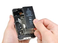
Use the edge of a plastic opening tool to gently pry the battery connector up from its socket on the logic board.
-
Remove the metal clip covering the antenna connector.
-
-
-
Pull up on the exposed clear plastic tab to peel the battery off the adhesive securing it to the iPhone.
-
If there's any alcohol solution remaining in the phone, carefully wipe it off or allow it to air dry before installing your new battery.
-
Remove the battery.
-
Before reassembly, clean metal-to-metal contact points with a de-greaser such as windex. The oils from your fingers have the potential to cause wireless interference issues.
-
Perform a hard reset after reassembly. This can prevent several issues and simplify troubleshooting.
Note that the pull tab is not actually attached to the battery. It is attached to the iPhone chassis, and is only used to separate the battery from the adhesive. (Don't expect it to come out with the battery!)
Also, the adhesive is VERY strong. I had to use my plastic opening tool to assist in prying the battery loose. This is probably the most nerve-wracking part of the job.
It is much easier to slightly WARM the battery with a HAIRDRYER not a HEAT GUN to soften the adhesive. DO NOT GET BATTERY HOT AND DO NOT USE HEAT GUN
Joe -
I just did this today. Everything was as scripted. Mine had lots of adhesive and had to use plastic spudger to go around battery to loosen up. Do not use plastic tab until you can see under battery a little bit. Great instructions. Took less than 10 minutes.
The adhesive is very strong and I was initially worried about damaging the phone by prying so much. There are a couple of places below the volume switch where you can pry between the metal of the case and the battery. If you lift the battery just a little, wiggle the pry bar further in and then start moving down the case. Don't worry about bending the battery, its dead anyway.
Do not pry on the left side (circuit board side) and do not use the pull tab until the adhesive is broken loose.
I tried this at first with a plastic pry tool, and the adhesive was so strong that I broke the tool. I then used a large screwdriver and applied pressure very slowly along various places on the outer side of the battery. That eventually did the trick.
-
-
-
Remove the two 1.8 mm Phillips screws securing the dock connector cable to the logic board.
-
Remove the thin metal dock connector cable cover.
-
-
-
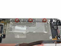
Remove the following five screws:
-
Three 1.3 mm Phillips screws
-
One 1.5 mm Phillips screw
-
One 2.4 mm Phillips screw
Careful here...On my phone, the little mounting screw boss (the part the screw threads into) of the top red-circled screw came unglued/welded from the underlying board, meaning the screw will no longer be able to be screwed back in.
The three 1.3 mm screws are very difficult to distinguish from the 1.5 mm screw. I spent a long time with a magnifying glass trying to tell them apart. For the other steps of the repair, I kept the screws in a tray compartment along with the piece that they connected, but for this step I recommend keeping each of the different types of screws separate.
-
-
-
-
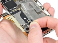
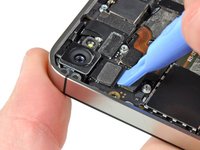
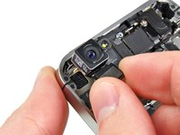
Use the edge of a plastic opening tool to pry the rear camera connector up from its socket on the logic board.
-
Remove the rear camera from the iPhone.
Better to delay removing the camera and its cable until the Display and Digitizer cables are removed as there is an arm on the right side of the camera that slips under the other cables.
I agree with ed -- move the camera removal step until after Step 16, after the digitizer and display cables have been removed, as there is a tab/arm on the camera's cable that should go under these two cables during reassembly.
-
-
-
Disconnect the five cables near the top of the logic board in the following order:
-
Headphone jack/volume button cable
-
Power button cable
-
Front facing camera cable
-
Digitizer cable
-
Display data cable
-
To disconnect the cables, use the edge of a plastic opening tool to gently lift their connectors up and out of the sockets on the logic board.
The Digitizer Cable on the new display seems to be too short. Trying to make it reach. It doesn't reach its place on the logic board. Going to disassemble and start over. (Step 15)
Any pointers?
What happened was there is a tab on the cable, and that didn't go all the way through the casing. I made this mistake about 3 times. It's not too short, just move the screen a little away from the casing, and pull the cable all the way through without ripping it.
⚠️ On reassembly, before plugging in the screen/digitizer cables, put the rear facing camera back in. There's a prong on the camera that lays underneath them.
-
-
-
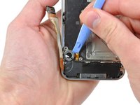
Remove the 1.5 mm Phillips #000 screw near the headphone jack.
take out screw on top of stand of first, then take of grounding plat, and then stand off.
This is correct.
Echoing the notes from 'boo' and Corey -- that's exactly what I saw too. Perhaps the guide should be updated?
This has been changed several times on the iphone 4 logic board manual, and the changes are always being reverted. There _IS_ a screw in step 16, but someone seems intent on not having it mentioned in the manual. Dunno why...
Because it's mentioned in Step 20.
It may have been mentioned in step 20 at some point, but it isn't anymore. The phillips head screw that's mentioned in step 20 is the one holding the grounding finger to the rear-facing camera corner of the motherboard.
That said, my concerns about step 16 have since been rectified, so I suppose step 20 could've been fixed at the same time.
There's a little rubber piece that you can see in the Step 17 & Step 21 pictures just above the yellow sticker. It fits over the edge of the board where the two ribbon cables from the display/digitizer come up through the board (Step 36). It's there to make sure the ribbon cables don't rub against the sharp edge of the board. This piece loves to fall out when pulling the logic board off. Make sure to put it back in when routing the cables in Step 36, thin edge on the bottom, thicker edge on the top.
-
-
-
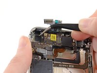
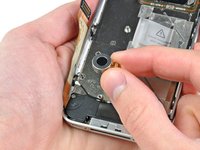
Lift the small grounding clip up off the logic board and remove it from the iPhone.
Can you show how this piece attaches?
-
-
-
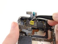
Use the edge of a plastic opening tool to disconnect the Wi-Fi antenna cable connector from the logic board.
For me, aligning the connector when putting things back together was the most difficult part of this repair. Unlike reattachment of the radio antenna in step 11, it is very difficult to see whether the male/female are aligned properly before applying pressure. Unfortunately, I have no secret as to how to accomplish this, other than to say that my WiFi is working after the repair.
-
-
Ferramenta utilizada neste passo:Standoff Screwdriver for iPhones$5.49
-
Remove the 2.5 mm Phillips #000 screw securing the logic board near the power button.
-
Remove the 4.8 mm standoff screw near the headphone jack.
I’d use a Phillips 00 instead of a flathead
-
-
-
Remove the 3.4 mm Phillips screw near the vibrator motor.
-
Remove the two 3.6 mm standoff screws along the side of the logic board nearest the battery opening.
When replacing the standoff screw closest to the dock connector, make sure it is tightened all the way down. The battery terminal screw fits in the standoff later, and if the standoff isn't tight (NOT TOO TIGHT!) then the battery will not be completely connected and your phone will power off unless tethered. This mimics a bad logic board symptom! Inspect this before replacing your logic board!
-
-
-
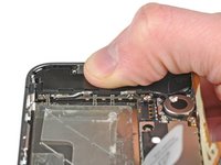
Carefully lift the logic board from the end closest to the speaker enclosure and slide it away from the top edge of the iPhone.
-
Remove the logic board.
When I was attempting to reinstall the logic board (step 21 in reverse), a small rubber bumper came loose from 'somewhere' on the board (I think). It isn't visible in any of the photos, so I really have no idea where it came from!
I don't see it in the pictures either, but I'm pretty sure there is a black bumper that rides on the 'top' of the logic board. I believe it reduces friction between the display/digitizer cables and the top of the logic board.
You can see this "bumper" in steps 16 and 20 (right above the yellow sticker in the pics), and it provides relief for the digitizer and display cables as they both come up and around the edge of the logic board. I put my bumper with its thicker side down towards the inside of the phone and it worked fine.
The rubber bumper has a groove in it, which rides a notch along the top edge of the logic board. Its purpose is to ease pressure between the top of the phone and the board. If you look at the top of the frame, there is a little horizontal ridge about 0.8cm (3/8") long which is just the right width of the rubber bumper.
For reference:
Your images show incorrect placement of the rubber spacer. Step 20 shows correct placement. It is just above the scan code sticker on the motherboard. That is where the ribbon cables roll over, so it makes sense.
I assume the thick side would be facing the rear of the phone, but can not be sure.?
I wouldn't use Windex. It's mostly water. Why would anyone put water on a connection? Use isopropyl alcohol and be certain that it's at least 95% alcohol.
Better yet use contact cleaner or the original Brakleen (in the RED can). You can find the Brakleen at any automotive store.
I experienced that when the rubber spacer had the thick side up towards the rear of the phone, the display data cable would plug in but had enough pressure from the rubber bumper pushing up that it would eventually become partially unplugged. This may not be immediately apparent while putting the phone back together because of still being partially plugged in. This was not an issue when the thin side was installed facing up towards the back of the phone.
-
-
Hope someone can ease my uncertainty: does the grounding finger for the
rear-facing camera go on TOP of the motherboard OR between the motherboard and
the standoff???
Under. There is nothing to ground if it went over the pcb. Look on the backside.
-
-
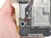
Use the edge of a plastic opening tool to pry the vibrator off the adhesive securing it to the frame of the iPhone.
-
Remove the vibrator.
For the record.... This thing was really REALLY stuck with adhesive when I removed it. Surprised I am the first to comment on this.
-
-
-
Remove the two 2.4 mm Phillips screws from the sides of the speaker enclosure assembly.
-
-
-
Remove the small plastic bracket that was installed under the screw closest to the dock connector cable.
My plastic corner bracket actually came out with the screw, so be aware this can happen
-
-
-
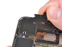
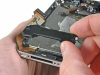
Remove the speaker enclosure assembly from the iPhone.
I can't find where the wifi grounding fingers go when reassembling. The picture isn't very helpful. Any ideas?
These Wi-Fi grounding fingers should be distinguished in the image that accompanies the instructions to show their location to ensure their identification to be cleaned and to be in the proper position upon reassembly. If I guess correctly, there is one by the screw on the left, two below the thumbnail in the image and a fourth that is blocked from view in the image by the logic board.
-
-
-
Remove the 1.6 mm Phillips screw securing the display assembly near the power button.
This isn't particularly easy. Maybe it's the screwdriver I have, but I can't seem to reach these corner screws.
No the problem is that you should probably remove the audio Jack. There is NO way you can unscrew that screw without stripping it without taking the audio jack out.
-
-
-
Remove the 1.6 mm Phillips screw near the headphone jack.
Nearly impossible to reinstall this screw when reassembling.
I was able to perform this step on my first repair attempt. Here's a tip: the rounded part of the headphone cable is very stiff and "spring" like. Just take a very thin Philips (#000) screwdriver and lay it down on the cable diagonally, pointing almost directly towards the screw. Push gently down on the cable and it will cave in somewhat. This is fine. Then you can go straight in at the screw and turn it out.
Photograph: http://i.imgur.com/wKigI.jpg
Thank you Bradley. I've had tons of grief with this screw in the past. I've just had to turn the driver at an angle and curse and yell and retry it 5 times before it worked. This is a MUCH better approach! I had no idea that cable safely had that much give. You have my gratitude.
AH, perhaps I jinxed myself, but I could not get this screw out. I think I stripped the phillips head too. Is there anything left to do to salvage it?
It's kind of frustrating that this guide doesn't include an optional headphone jack removal step or something, as I can't even do what Bradley suggested. I have the ifixit pro kit and the thin section of the shank on the bit isn't long enough to reach without removing it.
If needed, you can find instructions for removing the headphone jack here.
-
-
-
Remove the 1.6 mm Phillips screw near the dock connector cable.
-
-
-
Loosen the three large-headed Phillips screws along the volume button side of the iPhone about one half turn.
These screws are impossible to remove. Please help, what's the trick. I only could get one of them to loosen
Someone please help, I'm going to throw this thing across the room. cannot get these screws to loosen
You need a smaller screwdriver. One in my kit was too big spinning out the heads. Can also touch each screw with soldering iron if locktite is holding it but probably driver as they all came with the right driver.
-
-
-
Loosen the three large-headed Phillips screws along the other side of the iPhone about one half turn.
I found removing the three screws on one side during reassembly made it easier to keep the washers on the opposite side in the correct position when installing the display. When the display is in place, reinstall the three screws and then snug down all six. Then back all off about a quarter to a half turn to assist in aligning the holes for the four corner screws. Only after all ten screws are in place should the screws be tightened. Be sure to gently squeeze the display down to the outer frame at each screw while tightening to eliminate any gaps between the two.
That one corner screw is at the wrong angle what a pain stripping out the head of my driver/screw!
-
-
-
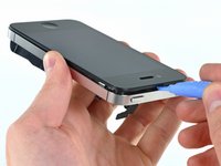
Use the edge of a plastic opening tool to gently pry up the display assembly around its perimeter.
-
De-route the digitizer and LCD cables through the steel inner frame.
-
When the front panel has been correctly installed, both the LCD and digitizer cables should be immediately next to one another and should be the same length, as shown in the second photo.
-
During reassembly, do not touch the metallic area at the base of the LCD data cable, as this can cause problems with the LCD. If you do touch it accidentally, clean it gently with an alcohol wipe before continuing.
DEFINITELY REMEMBER THE ABOVE ADVICE TO TRANSFER THE METAL MESH SCREEN FROM THE OLD SCREEN TO THE NEW ONE.
I've done this twice now, and it really, really stinks because you don't usually see it until the phone is all back together. That would mean doing the whole process again. Slapped myself in the forehead the second time.
Thank you so much for this easy to follow guide, but it's so good I don't usually look at the comments. Maybe this last little thing could be added.
Either way, Thanks Again.
took me about 2 hours to succesfully complete the entirety of this replacement. Although the hardest part is putting the screws back into their respective holes. And it does help to read the comments after reviewing the guide as well. It wasn't until I had the customer's phone completely back together that I realized that earpiece grill wasn't there on the new screen.. nevertheless.. Thank You to my favorite repair website for the easy to follow guides.
Well I got about 1/2 way back through the re-assembly and found that the digitizer cable was too short. I disassembled back to here and this time started snapping the new display surface back into place beginning at the end where the digitizer cable feeds through. Then I did a "dry-run" with the logic board to ensure the cable reaches and it looks good.
Instruction here refers to routing the digitizer/LCD cables through the
"outer case". Just for the sake of clarity,
isn't the part through which the ribbons are
being routed the FRAME? If it really IS the outer case, where is the "inner case"?
The digitizer/LCD cable warning is VERY important! I thought I had it right, but had to go back and disassemble again when I realized the digitizer connection wouldn't meet - it had folded under the frame (which I might have noticed if I'd compared it to the photo in Step 23 - that clearly shows that the 2 cables should be about the same length).
It's a great manual, and a satisfying repair - this iPhone had been run over, the front glass totally shattered, and now it's operational!
Got my phone back together and cut it on and the screen is white with a couple pixels in upper left hand corner that are black. I could very faintly make out the screen after it booted up and was able to power it down. Any recommendations on how to proceed. I plan to disassemble and check all the connections.
Same problem as Rachael. I've removed all the screws but the front glass isn't budging despite my spudging. Any tricks for resolving this? I don't want to break it at this point.
Use the guitar pick or a fingernail file to pry up one of the corners (the plastic goes with the glass away from the metal frame). Then carefully pull up the whole screen. There are plastic "feet" that are holding the screen on, you'll have to pry up an edge to get them to let go.
rafesmom -
I had a lot of broken glass stuck to the adhesive after removing the screen. Be sure you use tweezers and a scraper (be careful) to remove all the old debris prior to installing the new part. I got my part from ifixit so it had the mesh and the ring for the camera on the new part.
During the whole replacement of everything process, I ripped off the cable for the digitizer from the main cable, is there any way to repair this or should I just order a new screen?
Reassembly Warning: Be careful routing the cables through the frame. The digitizer cable tears easily. The LCD cable has the square shield. So, the digitizer cable is the cable without the shield. On the digitizer cable there is a section where the cable is wide then it gets more narrow. Where it tapers down (gets narrow) the cable can tear at this point. If the digitizer cable is torn the touch screen feature will not work.
There's adhesive top and bottom which gave me a large struggle spooning off the screen. My LCD cable was short due to it folding take it apart again uggg
The warning regarding tearing of the cable cannot be overemphasized. I tore a brand new cable on installation and had to hang my head in shame after having to reinstall a broken screen until I got another new part.
It’s best to put the plastic ring around the lens before assembly. The assembly I got from ifixit had the ring oriented wrong and interfered with the glass laying flush. I removed it with a drop of alcohol and rotated it around the lens until it slid in flush.
Take out the 6 side screws/washers. Put the four corner screws in loose and then thread in the 6 screws/washers. Once all are threaded in then tighten. It’ll save you a lot of grief.
-
-
-
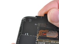
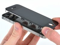
Remove the display assembly from the iPhone.
-
You may have to reuse the earpiece grille and the clear plastic ring around the front facing camera from the old/damaged assembly. This will depend on where you buy the replacement part.
-
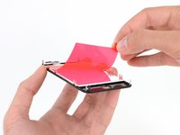
Your replacement display may come with colored plastic film on the back of the LCD. If so, use the pull tab near the home button to peel the plastic film from the LCD before installing the new display in your iPhone.
-
After reassembly, note the following:
-
Clean the touchscreen surface with an alcohol wipe prior to turning the iPhone back on. The alcohol helps dissipate any lingering static electricity, which can cause problems with the display.
When I put it all bck together the phone itself comes on but the screen won't come on... did I do something wrong?
-
-
-
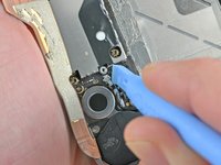
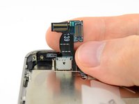
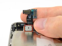
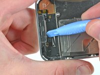
Use a clean fingernail or the edge of a plastic opening tool to flip up the retaining flap on the home button ribbon cable.
The plastic tool is too large and cumbersome. I just destroyed the connector. Now What!
-
-
-
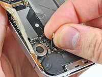
Carefully de-route the home button cable through its slot in the outer case and remove it from the iPhone.
-


To reassemble your device, follow these instructions in reverse order.
To reassemble your device, follow these instructions in reverse order.
Cancelar: não concluí este guia.
129 outras pessoas executaram este guia.

3 comentários
How can a company that prides itself on simplicity and elegance make something so needlessly unserviceable? I don't mind the small screws, even if I wonder how many of them really need to be there... but the fragile cables, little black spacers, the pentalobe screws and the glue - oh the inhumanity of the glue! The only thing that makes me happy is, now that Tim Cook's decided that they're going to service these things in-store, the thought of Apple employees sending an earful of expletives up the management chain.
Small and fragile = lite weight. And all of those spacers and glue is to keep everything in place and prevent those small and fragile parts from breaking as you use the phone. If you want a tiny, lite phone there are compromises. And Apple's mantra has never been serviceability. It's about getting you to upgrade to the new cool thing every 1-2 years, way before the phone would normally need servicing. And the Apple store really only services new batteries and screens. For pretty much everything else they just give you a new phone.
J V -
is there a way to remove the button without replacing the cable?
Pra descarregar a bateria, antes de fazer o serviço, isso serve pra qualquer celular?
Gilmar Dutra - Responder