Introdução
Use this guide to replace the motherboard in an Xbox Series X.
You can also use this guide to reapply thermal paste in your Xbox.
Before you begin, completely power down and unplug all cables from your console. Remember to follow general electrostatic discharge (ESD) safety procedures while repairing the console.
O que você precisa
-
-
Use a pair of tweezers to remove the sticker hiding the first screw on the back panel, near the base.
-
-
Ferramenta utilizada neste passo:Magnetic Project Mat$19.95
-
Use a T8 Torx driver to remove the two 7.4 mm‑long screws securing the back panel.
-
-
-
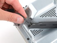
Insert the flat end of a spudger into the gap between the back panel and the shell, near the left side of the base.
-
Pry up the back panel to release it from the locking clips.
-
-
-
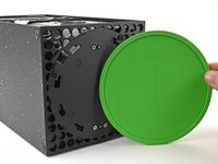
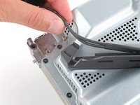
Grip the back panel at the opening you just created and pull it up and away from the shell to unclip the long edges.
-
-
-
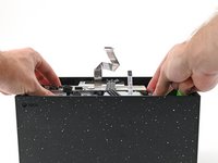
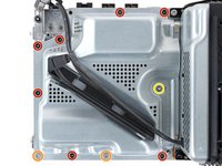
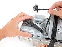
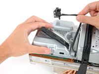
Use a T8 Torx driver to remove the three screws securing the fan to the center chassis:
-
One 10.5 mm pancake screw
-
Two 8.8 mm screws
-
-
Ferramenta utilizada neste passo:Tweezers$4.99
-
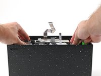
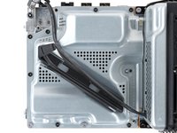
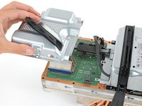
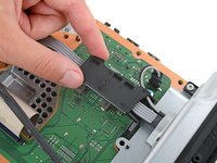
Use your fingers or a pair of blunt tweezers to grip the edges of the fan cable connector, and pull up to disconnect it from the center chassis.
-
-
-
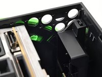
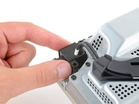
Use the flat end of a spudger to lift up on the locking tab holding the base to the shell.
-
-
-
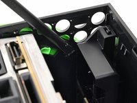
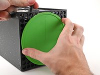
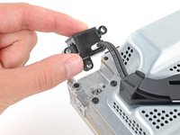
With the locking tab held open, grip the base and rotate it counterclockwise to unlock it from the shell.
-
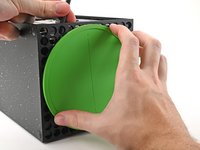
Remove the base.
-
-
-
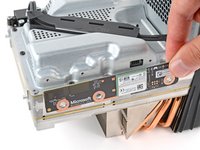
Use a T8 Torx driver to remove the two 8.8 mm screws securing the optical drive's vibration isolator to the shell: one on the base and one on the top of the isolator.
-
-
-
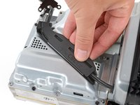
Lift up the optical drive's vibration isolator to remove it.
-
-
Ferramenta utilizada neste passo:Tweezers$4.99
-
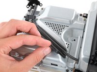
Use a pair of blunt tweezers to grip the edges of the optical drive power connector and pull up to disconnect it from the optical drive.
-
Use your fingers to pull up and disconnect the data cable from the optical drive.
-
-
-
Grip the top edge of the optical drive and pull it out of its slot in the shell to remove it.
-
-
-
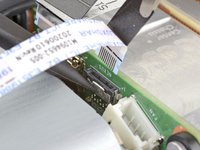
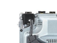
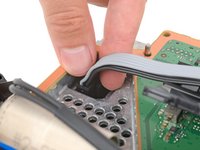
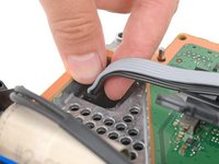
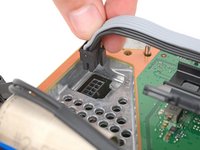
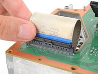
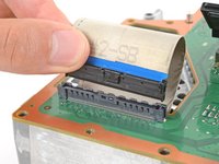
Use the flat end of a spudger to flip open the metal locking tab on the USB port ribbon cable.
-
-
-
-
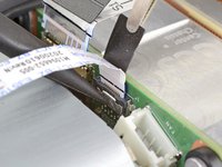
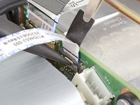
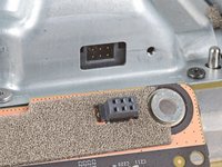
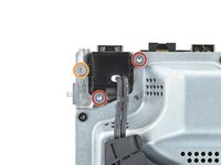
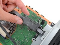
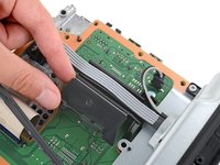
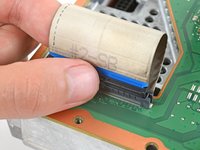
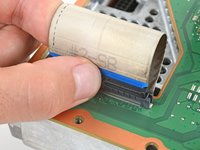
Use the pointed end of a spudger to depress the metal tab on the side of the power button cable's board connector.
-
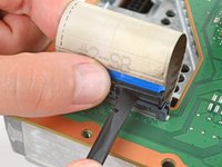
With the metal tab depressed, use a pair of tweezers to pull up on the pull tab to disconnect the power button cable from the center chassis.
-
Don't pull on the cable without depressing the metal tab, otherwise you risk damaging either the cable or the connector.
-
-
-
Use a T8 Torx driver to remove the three 7.4 mm screws securing the center chassis assembly to the shell.
-
-
-
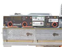
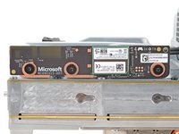
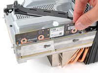
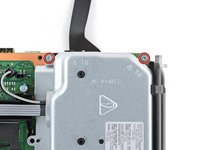
Use a T8 Torx driver to remove the three 9.6 mm‑long screws securing the antenna board to the center chassis.
-
-
-
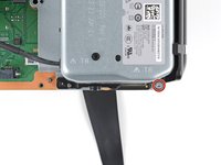
Grip the top right corner of the antenna board and pull it directly away from the center chassis to disconnect it.
-
-
-
Use a T8 Torx driver to remove the three screws securing the power cable port to the chassis:
-
Two 13.1 mm‑long screws
-
One 35 mm‑long screw
-
-
-
Unlatch and open the lid on the power cable's plastic guide.
-
-
-
Use a T8 Torx driver to remove the ten screws securing the board shield:
-
Seven 8.7 mm‑long screws
-
Two 35 mm‑long screws
-
One 13 mm‑long screw
-
-
-
Open the lid on the power supply's plastic cable guide.
-
-
-
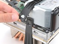
Use your fingers to pinch the locking tab in the center of the interconnect cable connector.
-
While pinching the tab, insert the flat end of a spudger between the top of the socket and the connector's tab.
-
Twist the spudger to lift the connector out of its socket until the clip in the center disengages.
-
-
-
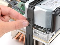
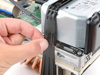
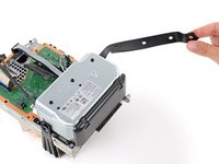
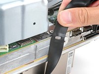
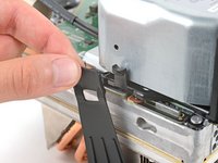
Pull the rubber strap down and away from the chassis to unlatch it.
-
-
-
Use a T8 Torx driver to remove the three 35 mm‑long silver screws from the power supply—leave the fourth black screw in place.
-
-
-
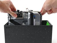
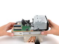
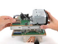
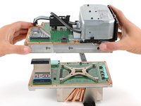
Grip the edges of the center chassis (not the power supply) and lift it off the motherboard and heatsink assembly, routing the interconnect cable through its cutout.
-
-
-
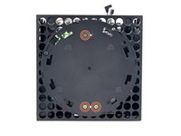
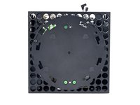
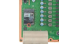
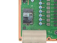
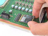
Use a T8 Torx driver to remove the 5.1 mm‑long screw securing the SSD.
-
-
-
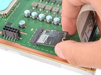
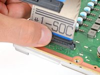
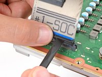
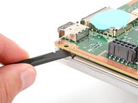
Pinch the locking tab on the interconnect cable on the motherboard and use the flat end of a spudger to disengage the clip.
-
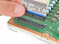
Use your fingers to pull the connector straight up and out of its socket.
-
-
-
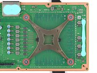
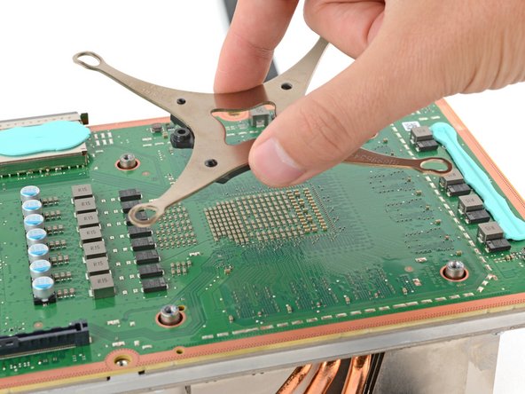
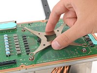
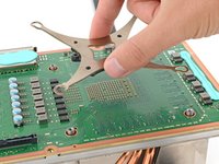
Use a T8 Torx driver to remove the four 12.4 mm‑long APU tension bracket screws.
-
-
-
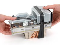
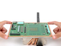
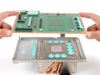
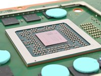
Use your fingers to lift the motherboard straight up and off the heatsink to remove it.
-
-
-
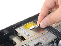
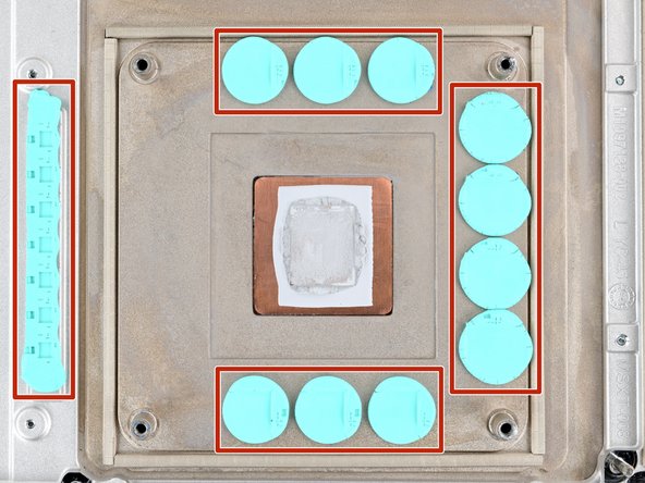
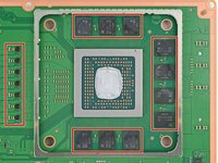
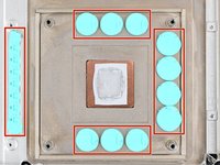
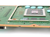
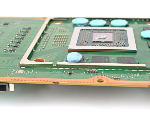
Check the condition of the thermal putty—it'll be on the heatsink and/or the motherboard.
-
If any pieces are damaged or dried out, follow the next four steps to remove and replace them.
-
If you're only replacing the thermal paste, skip to this step.
-
-
-
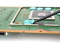
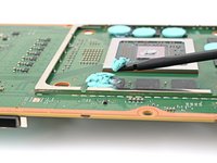
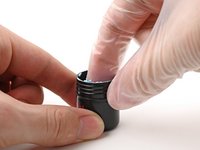
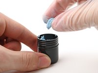
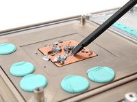
Roll the thermal putty into a ball.
-
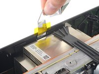
Place the thermal putty where the damaged thermal pad was, making sure it's centered over the component—in this case a memory chip.
-
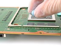
Optionally, you can use the flat end of a spudger (or an included applicator) to spread the thermal putty over the surface of the component.
-
-
Ferramenta utilizada neste passo:Cotton Swabs$4.99
-
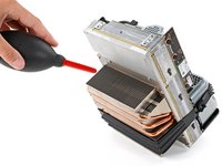
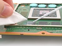
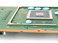
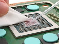
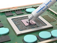
Apply a few drops of isopropyl alcohol (>90%) to the processor and use a coffee filter or a lint-free cloth to wipe away any residue.
-
-
-
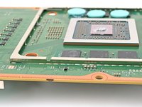
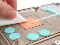
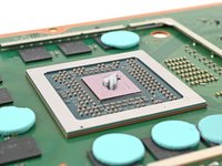
Apply a small bead of thermal paste to the center of the APU.
-


To reassemble your device, follow these instructions in reverse order.
Take your e-waste to an R2 or e-Stewards certified recycler.
Repair didn’t go as planned? Try some basic troubleshooting, or ask our Xbox Series X Answers community for help.
To reassemble your device, follow these instructions in reverse order.
Take your e-waste to an R2 or e-Stewards certified recycler.
Repair didn’t go as planned? Try some basic troubleshooting, or ask our Xbox Series X Answers community for help.

