Esta versão pode conter edições incorretas. Mude para o último instantâneo verificado.
O que você precisa
-
Este passo não foi traduzido. Ajude a traduzi-lo
-
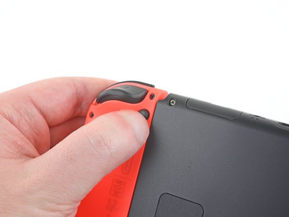
Press and hold down the small round button on the back of the Joy Con controller.
-
While you hold down the button, slide the controller upward.
-
-
Este passo não foi traduzido. Ajude a traduzi-lo
-
Continue sliding the Joy Con upward until it's completely removed from the console.
-
-
Este passo não foi traduzido. Ajude a traduzi-lo
-
Use a Y00 screwdriver to remove the four 6.3 mm-long screws securing the rear panel.
-
-
Este passo não foi traduzido. Ajude a traduzi-lo
-
Use a JIS 000 driver or an official iFixit PH 000 driver to remove the following screws securing the rear panel:
-
One 2.5 mm-long screw on the top edge of the device
-
Two 2.5 mm-long screws on the bottom edge of the device
-
-
Este passo não foi traduzido. Ajude a traduzi-lo
-
Use a JIS 000 screwdriver or an official iFixit PH 000 driver to remove the two 3.8 mm center screws on the sides of the device (one on each side).
-
-
Este passo não foi traduzido. Ajude a traduzi-lo
-
Use your finger to flip up the kickstand on the back of the device.
-
-
-
Este passo não foi traduzido. Ajude a traduzi-lo
-
Use a JIS 000 screwdriver or an official iFixit PH 000 driver to remove the 1.6 mm screw in the kickstand well.
-
Close the kickstand.
-
-
Este passo não foi traduzido. Ajude a traduzi-lo
-
Open the game card cartridge flap.
-
Lift the rear panel up from the bottom of the device and remove it.
-
-
Este passo não foi traduzido. Ajude a traduzi-lo
-
Use a JIS 000 screwdriver or an official iFixit PH 000 driver to remove the 3.1 mm screw securing the microSD card reader to the device.
-
-
Este passo não foi traduzido. Ajude a traduzi-lo
-
Use your fingers or a pair of tweezers to lift the microSD card reader straight up from the device to disconnect and remove it.
-
-
Este passo não foi traduzido. Ajude a traduzi-lo
-
Use a JIS 000 screwdriver or an official iFixit PH 000 driver to remove the six 3 mm screws securing the shield plate to the device.
-
-
Este passo não foi traduzido. Ajude a traduzi-lo
-
Use your fingers or a pair of tweezers to peel back the piece of foam on the top edge of the device near the fan exhaust port.
-
-
Este passo não foi traduzido. Ajude a traduzi-lo
-
Insert a spudger underneath the shield plate along the edge of the device.
-
Pry up to lift the shield plate and remove it from the device.
-
You can reuse the pink thermal compound if you're careful. Keep the compound clean and make sure it makes solid contact between the heat sink and the shield during reassembly.
-
If you need to replace it, refer to our thermal paste guide to remove the old thermal compound and replace it with an appropriate compound, such as K5 Pro, during reassembly.
-
-
Este passo não foi traduzido. Ajude a traduzi-lo
-
Use the point of a spudger to pry the battery connector straight up and out of its socket on the motherboard.
-
-
Este passo não foi traduzido. Ajude a traduzi-lo
-
Use a spudger, opening tool, or your fingernail to flip up the small, hinged locking flap on the Joy Con rail data cable's ZIF connector.
-
-
Este passo não foi traduzido. Ajude a traduzi-lo
-
Use a pair of tweezers to slide the Joy Con rail data cable out of its connector on the motherboard.
-
-
Este passo não foi traduzido. Ajude a traduzi-lo
-
Use a JIS 000 screwdriver or an official iFixit PH 000 driver to remove the four 3.7 mm screws securing the right Joy Con rail to the frame of the device.
-
Cancelar: não concluí este guia.
71 outras pessoas executaram este guia.
13 comentários
Would you happen to know how to take out the screws if they’ve been stripped due to corrosion/rust? The back and site plate screws seem to have corroded and started to strip when I tried to unscrew them.
I am running into same problem now. 3 out of 4 back screws are striped
Same issue for me as well, my husband pretty much just brute strengths through them for me until I can get replacement screws. Not the most sophisticated method, but effective.
This was a wonderful guide. Its straight forward, simple to understand, and doesnt pass over any steps large or small. Thank you to your team for what you do for us all.


