Esta versão pode conter edições incorretas. Mude para o último instantâneo verificado.
O que você precisa
-
Este passo não foi traduzido. Ajude a traduzi-lo
-
Use a Y00 screwdriver to remove the four 6.3 mm-long screws securing the back panel.
-
-
Este passo não foi traduzido. Ajude a traduzi-lo
-
Use a JIS 000 driver or an official iFixit PH 000 driver to remove the following screws securing the back panel:
-
Two 3.6 mm-long screws on the top of the device
-
Two 3.6 mm-long screws on the bottom of the device
-
-
Este passo não foi traduzido. Ajude a traduzi-lo
-
Insert an opening tool into the left speaker grille on the bottom of the device.
-
Twist the opening tool to release the clips securing the back panel.
-
-
Este passo não foi traduzido. Ajude a traduzi-lo
-
Slide the opening tool around the bottom-left corner to release the clips on the left side of the device.
-
-
Este passo não foi traduzido. Ajude a traduzi-lo
-
Insert an opening tool into the right speaker grille on the bottom of the device.
-
Twist the opening tool to release the clips.
-
-
Este passo não foi traduzido. Ajude a traduzi-lo
-
Slide and pry the opening tool around the bottom-right corner to release the clips on the right side of the device.
-
-
Este passo não foi traduzido. Ajude a traduzi-lo
-
Continue sliding and prying the opening tool along the gap on the top of the device to release the clips.
-
-
Este passo não foi traduzido. Ajude a traduzi-lo
-
Lift the bottom edge of the back panel, opening it like a book.
-
Remove the back panel.
-
-
Este passo não foi traduzido. Ajude a traduzi-lo
-
Use a JIS 000 driver or an official iFixit PH 000 driver to remove the following four screws:
-
Three 3.1 mm screws
-
One 4.5 mm screw
-
-
Este passo não foi traduzido. Ajude a traduzi-lo
-
Use a spudger or your fingers to lift the shield plate up and out of the device.
-
Remove the shield plate.
-
-
-
Este passo não foi traduzido. Ajude a traduzi-lo
-
Use an opening tool or your fingernail to flip up the small, hinged locking flap on the motherboard interconnect cable's ZIF connector.
-
-
Este passo não foi traduzido. Ajude a traduzi-lo
-
Use a pair of tweezers to slide the interconnect cable out of its connector on the motherboard.
-
-
Este passo não foi traduzido. Ajude a traduzi-lo
-
Use the point of a spudger to pry the battery connector straight up and out of its socket on the motherboard.
-
-
Este passo não foi traduzido. Ajude a traduzi-lo
-
Use a pair of tweezers or your fingers to pull the left speaker cable straight up and out of its socket on the daughterboard.
-
-
Este passo não foi traduzido. Ajude a traduzi-lo
-
Use a JIS 000 driver or an official iFixit PH 000 driver to remove the 4.5 mm screw securing the left speaker module.
-
-
Este passo não foi traduzido. Ajude a traduzi-lo
-
Use your fingers to lift the speaker module up and out of its recess to remove it.
-
-
Este passo não foi traduzido. Ajude a traduzi-lo
-
Use an opening tool or your fingernail to flip up the small, hinged locking flap on the motherboard interconnect cable's ZIF connector.
-
-
Este passo não foi traduzido. Ajude a traduzi-lo
-
Use a pair of tweezers to slide the motherboard interconnect cable out of its connector on the daughterboard.
-
-
Este passo não foi traduzido. Ajude a traduzi-lo
-
Use an opening tool or your fingernail to flip up the small, hinged locking flaps on the two ribbon cable ZIF connectors.
-
-
Este passo não foi traduzido. Ajude a traduzi-lo
-
Use a pair of tweezers to slide the daughterboard screen cable out of its connector on the motherboard.
-
Repeat this procedure for the volume buttons cable.
-
-
Este passo não foi traduzido. Ajude a traduzi-lo
-
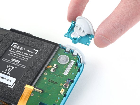
Use a pair of tweezers or your fingers to remove the volume buttons.
-
-
Este passo não foi traduzido. Ajude a traduzi-lo
-
Use an opening tool or your fingernail to flip up the small, hinged locking flap on the left joystick cable's ZIF connector.
-
-
Este passo não foi traduzido. Ajude a traduzi-lo
-
Use a pair of tweezers to slide the left joystick cable out of its connector on the daughterboard.
-
-
Este passo não foi traduzido. Ajude a traduzi-lo
-
Use a JIS 000 driver or an official iFixit PH 000 driver to remove the two 4.5 mm screws securing the left trigger button assembly.
-
-
Este passo não foi traduzido. Ajude a traduzi-lo
-
Use a JIS 000 driver or an official iFixit PH 000 driver to remove the following four screws:
-
Two 4.5 mm screws
-
Two 6 mm screws
-
-
Este passo não foi traduzido. Ajude a traduzi-lo
-
Use your fingers to lift the daughterboard up and out of its recess to remove it.
-
-
Este passo não foi traduzido. Ajude a traduzi-lo
-
Use a JIS 000 driver or an official iFixit PH 000 driver to remove the two 3.5 mm screws securing the left joystick.
-
-
Este passo não foi traduzido. Ajude a traduzi-lo
-
Use the flat end of a spudger to lift the joystick up and out of its recess.
-
Use your fingers to remove the joystick.
-


Cancelar: não concluí este guia.
95 outras pessoas executaram este guia.

35 comentários
Really appreciate the detailed pictures.
This was great, I love how every step was so simply broken down and had pictures. Thank you, my son is very happy to have his switch back in action.
I followed this guide, bought the tools and replacement part, after successfully doing the replacement, my switch light now won’t power on at all, how can I fix this? any help please…
Hi Iczleal I had the same issue when I first did it and then I went back step by step. Turns out I didn’t plug the battery back in correctly, I recommend just repeating the steps and checking to see if everything is connected properly. Hope this helps :)