Introdução
Use this guide to remove or replace the volume and power buttons in a Microsoft Surface Pro 5.
Applying new thermal paste to the CPU during reassembly may improve the performance of your Surface. If you wish to do that, make sure you have new thermal paste and either high-concentration isopropyl alcohol or a specialized thermal paste cleaner.
There is a significant chance that you may break the unreinforced and fragile display panel during this procedure. Be sure to apply plenty of heat and be extremely careful during the prying stage.
O que você precisa
-
-
If the screen's glass is cracked, keep further breakage contained and prevent bodily harm during your repair by taping over the glass. Lay overlapping strips of clear packing tape over the display until all the glass is covered. Wear safety glasses to protect your eyes.
-
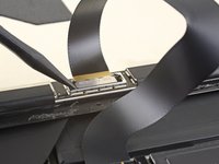
Heat an iOpener and apply it to the right edge of the Surface's screen for two minutes.
-
-
-
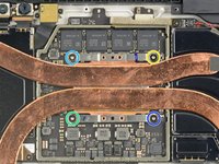
Take note of the screen adhesive layout before continuing:
-
These areas only contain adhesive and are safe to cut.
-
The display board and flex cables sit here close to the edge. Cut very carefully and do not insert the pick as deep under the display.
-
Fragile antenna cables lie under this part of the screen. Carefully follow the procedure to avoid damaging them. The adhesive is also the thickest here.
-
-
-
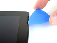
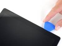
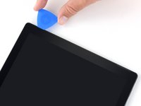
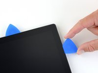
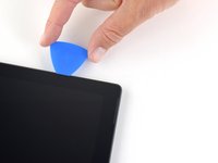
Insert an opening pick into the speaker opening on the screen and slide the pick under the glass. Do not press the pick into the speaker grille, as the grille is easily torn.
-
-
-
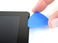
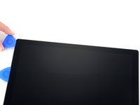
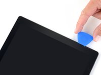
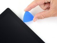
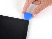
Rotate the pick toward the bottom of the Surface to slide it underneath the lower edge of the speaker cutout.
-
-
-
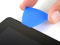
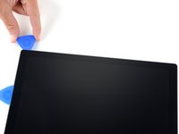
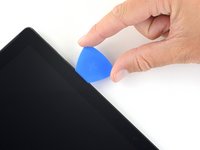
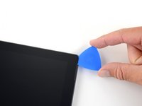
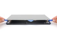
Slide the pick down the right edge of the Surface to slice through the adhesive under the screen.
-
Leave this opening pick in the right edge to prevent the adhesive from resealing.
-
-
-
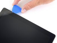
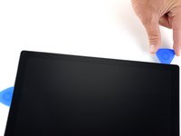
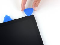
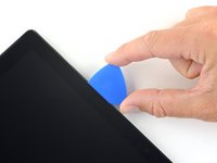
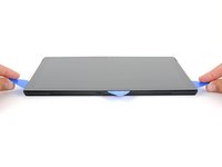
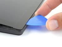
Insert the point of a pick under the display where you just stopped cutting. Do not insert the pick deeper than the edge of the bezel.
-
Carefully roll the pick to the right, pressing the long edge of the pick into the screen adhesive underneath the bezel, cutting the adhesive as you go. Do not slide the pick along the edge of the Surface.
-
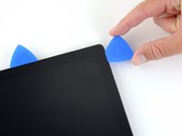
Repeat this motion of inserting the point of the pick where you just cut, and rolling to the right all along the top edge of the Surface, until the pick is 2.5 inches (64 mm) from the right edge of the Surface.
-
-
-
-
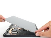
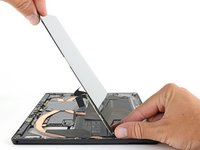
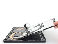
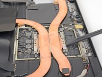
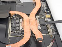
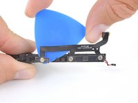
Very slowly lift the screen assembly away from the Surface case. If you encounter any resistance, stop and check that all the adhesive is separated.
-
Use an opening pick to cut through any remaining adhesive.
-
-
-
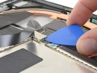
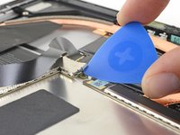
Use an opening pick to pry up one edge of the EMI shield covering the display board.
-
Repeat this procedure at different points around the shield until it is free.
-
-
Ferramenta utilizada neste passo:Tweezers$4.99
-
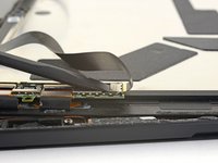
Insert one point of a pair of pointed tweezers into a gap in the edge of the EMI shield covering the digitizer connector.
-
Use the tweezers to pry the EMI shield away from the display as much as you can without bending it.
-
Repeat this procedure at different points around the shield until it is free. Remove the shield.
-
-
-
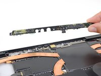
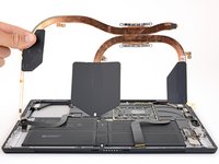
Remove the screen assembly from the Surface.
-
During reassembly, pause here and follow this guide to replace the screen adhesive.
-
-
-
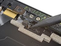
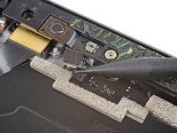
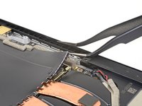
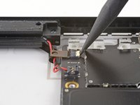
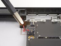
Use the point of a spudger to pry the microphone connector straight up and out of its socket on the motherboard.
-
-
-
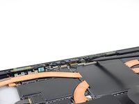
Use a T5 Torx driver to remove the four screws securing the antenna support:
-
Three 4.5 mm screws
-
One 6 mm screw
-
-
-
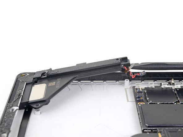
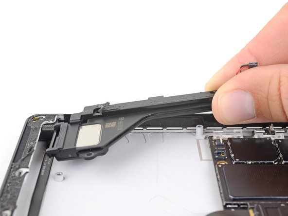
Use a spudger to lift the antenna support out of its recess in the Surface.
-
Remove the antenna support.
-
-
Ferramenta utilizada neste passo:Tweezers$4.99
-
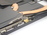
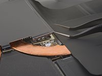
Insert one point of a pair of pointed tweezers into a gap in the corner of the EMI shield covering the heat sink.
-
Use the tweezers to pry the EMI shield away from the motherboard as much as you can without bending it. Do not remove it yet.
-
-
-
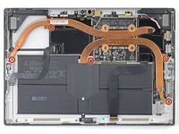
Remove the nine Torx screws securing the heat sink:
-
Five 2.6 mm-long T3 screws
-
Four 3.3 mm-long T5 screws
-
Screw 1
-
Screw 2
-
Screw 3
-
Screw 4
-
-
-
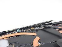
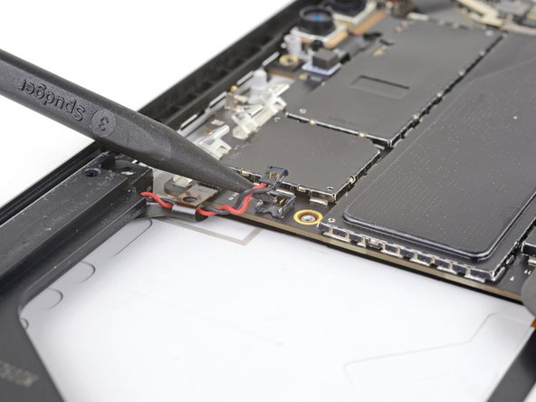
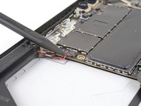
Use the point of a spudger to lift the left speaker connector out of its socket on the motherboard.
-
-
-
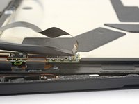
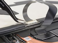
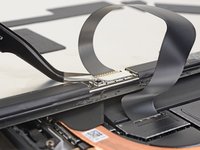
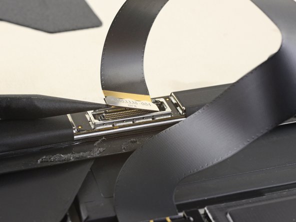
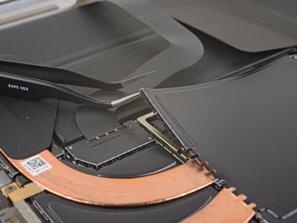
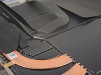
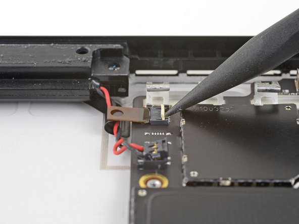
Use the point of a spudger to flip up the small locking flap securing the volume and power button cable ZIF connector.
-
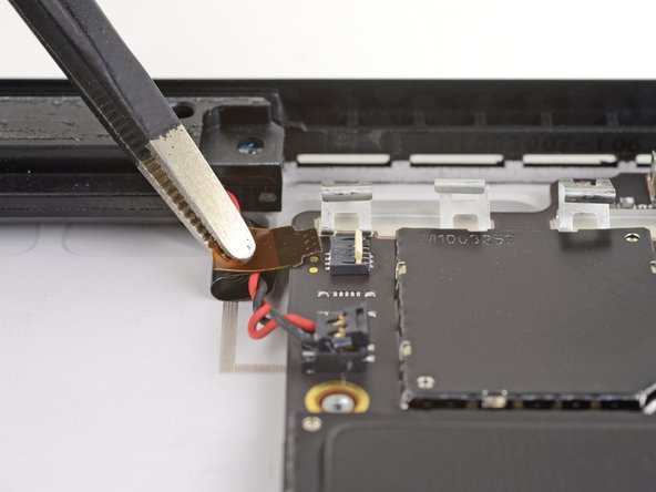
Slide the volume and power button cable straight out of its socket on the motherboard.
-
-
-
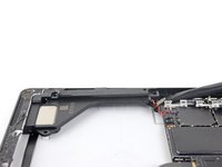
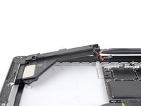
Use a T5 Torx driver to remove the two screws securing the left speaker:
-
One 6 mm screw
-
One 3.9 mm screw
-
-
-
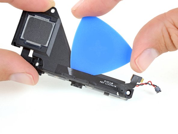
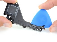
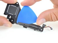
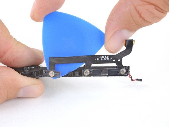
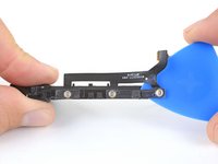
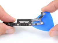
Heat an iOpener and apply it to the long edge of the speaker assembly for two minutes to soften the adhesive securing the buttons.
-


Compare your new replacement part to the original part—you may need to transfer remaining components or remove adhesive backings from the new part before installing.
To reassemble your device, follow the above steps in reverse order.
Take your e-waste to an R2 or e-Stewards certified recycler.
Repair didn’t go as planned? Try some basic troubleshooting, or ask our Answers community for troubleshooting help.
