Esta versão pode conter edições incorretas. Mude para o último instantâneo verificado.
O que você precisa
-
Este passo não foi traduzido. Ajude a traduzi-lo
-
Remove the following ten screws securing the lower case to the upper case:
-
Seven 3 mm Phillips screws.
-
Three 13.5 mm Phillips screws.
-
-
Este passo não foi traduzido. Ajude a traduzi-lo
-
Using both hands, lift the lower case near the vent to pop it off two clips securing it to the upper case.
-
Remove the lower case and set it aside.
-
-
Este passo não foi traduzido. Ajude a traduzi-lo
ComprarFerramenta utilizada nesse passo:P6 Pentalobe Screwdriver 2009 15" MacBook Pro Battery$5.49-
Remove the two 5-Point Pentalobe screws along the top edge of the battery.
-
-
Este passo não foi traduzido. Ajude a traduzi-lo
-
Use the tip of a spudger to bend back the finger of the "Warning: Do not remove the battery" sticker while you remove third five-point Pentalobe screw hidden underneath.
-
-
Este passo não foi traduzido. Ajude a traduzi-lo
-
Lift the battery by its plastic pull tab and slide it away from the long edge of the upper case.
-
-
Este passo não foi traduzido. Ajude a traduzi-lo
-
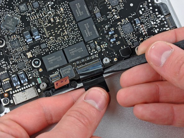
Tilt the battery back enough to access the battery cable connector.
-
Pull the battery cable connector away from its socket on the logic board and remove the battery from the upper case.
-
-
Este passo não foi traduzido. Ajude a traduzi-lo
-
Use a spudger to pry the fan connector straight up off the logic board.
-
-
Este passo não foi traduzido. Ajude a traduzi-lo
-
Remove the three T6 Torx screws securing the left fan to the logic board.
-
Lift the fan out of the upper case.
-
-
Este passo não foi traduzido. Ajude a traduzi-lo
-
Use the flat end of a spudger to disconnect the left fan connector from the logic board.
-
-
Este passo não foi traduzido. Ajude a traduzi-lo
-
Remove the three T6 Torx screws securing the left fan to the logic board.
-
Lift the left fan out of the upper case.
-
-
Este passo não foi traduzido. Ajude a traduzi-lo
-
Hold the end of the cable retainer down with one finger while you use the tip of a spudger to slightly lift the other end and rotate it away from the camera cable connector.
-
Disconnect the camera cable by pulling the male end straight away from its socket.
-
-
Este passo não foi traduzido. Ajude a traduzi-lo
-
Disconnect the camera cable by pulling the male end straight away from its socket.
-
-
Este passo não foi traduzido. Ajude a traduzi-lo
-
Use the flat end of a spudger to pry the optical drive cable connector up off the logic board.
-
-
Este passo não foi traduzido. Ajude a traduzi-lo
-
Using the flat end of a spudger, pry the subwoofer connector straight up from the connector jack.
-
-
Este passo não foi traduzido. Ajude a traduzi-lo
-
Use the flat end of a spudger to pry the hard drive/IR sensor cable connector up off the logic board.
-
-
Este passo não foi traduzido. Ajude a traduzi-lo
-
Remove the two 1.5 mm Phillips screws securing the cable cover to the logic board.
-
Lift the cable cover out of the upper case.
-
-
-
Este passo não foi traduzido. Ajude a traduzi-lo
-
Use a spudger to pry the trackpad flex ribbon cable connector up off the logic board.
-
-
Este passo não foi traduzido. Ajude a traduzi-lo
-
Use your fingernail to flip up the locking flap on the ZIF socket for the keyboard ribbon cable. The locking flap is located at the opposite side of the socket compared to the keyboard ribbon cable. Hook your fingernail under it and carefully lift it up vertically.
-
Use the tip of a spudger to slide the keyboard ribbon cable out of its socket.
-
-
Este passo não foi traduzido. Ajude a traduzi-lo
-
Use a spudger to pry the battery indicator ribbon cable connector up off the logic board.
-
-
Este passo não foi traduzido. Ajude a traduzi-lo
-
Remove the single 7 mm Phillips screw securing the display data cable retainer to the upper case.
-
Remove the display data cable retainer from the upper case.
-
-
Este passo não foi traduzido. Ajude a traduzi-lo
-
Grab the plastic pull tab secured to the display data cable lock and rotate it toward the DC-in side of the computer.
-
-
Este passo não foi traduzido. Ajude a traduzi-lo
-
Pull the display data cable connector straight away from its socket.
-
-
Este passo não foi traduzido. Ajude a traduzi-lo
-
Using the tip of a spudger, flip up the keyboard backlight ribbon cable retaining flap.
-
Pull the keyboard backlight ribbon cable straight out of its socket.
-
-
Este passo não foi traduzido. Ajude a traduzi-lo
-
Remove the following screws:
-
Seven 3.3 mm T6 Torx screws securing the logic board to the upper case.
-
Two 8 mm T6 Torx screws securing the DC-In board to the upper case.
-
-
Este passo não foi traduzido. Ajude a traduzi-lo
-
Carefully lift the logic board assembly from the left side and work it out of the upper case, minding the port side that may get caught during removal.
-
-
Este passo não foi traduzido. Ajude a traduzi-lo
-
Lift the logic board enough to gain clearance and use a spudger to pry the microphone up off the upper case.
-
Slide the logic board away from the port openings and lift the assembly out of the upper case.
-
-
Este passo não foi traduzido. Ajude a traduzi-lo
-
Slide the logic board away from the port openings and lift the assembly out of the upper case.
-
-
Este passo não foi traduzido. Ajude a traduzi-lo
-
Remove the two Phillips screws securing the hard drive bracket to the upper case.
-
Remove the hard drive bracket from the upper case.
-
-
Este passo não foi traduzido. Ajude a traduzi-lo
-
Using its attached tab, lift the free end of the hard drive and pull it away from the edge of the upper case.
-
-
Este passo não foi traduzido. Ajude a traduzi-lo
-
Pull the hard drive cable connector away from the body of the hard drive.
-
Remove the hard drive and set it aside.
-
-
Este passo não foi traduzido. Ajude a traduzi-lo
-
Carefully peel the hard drive cable off the adhesive securing it to the right speaker housing.
-
-
Este passo não foi traduzido. Ajude a traduzi-lo
-
Remove the following four screws securing the hard drive and IR sensor cable to the upper case:
-
Two 1.5 mm Phillips screws.
-
Two 4 mm Phillips screws.
-
-
Este passo não foi traduzido. Ajude a traduzi-lo
-
Slide the hard drive and IR sensor bracket away from the edge of the upper case.
-
-
Este passo não foi traduzido. Ajude a traduzi-lo
-
Carefully peel the IR sensor/sleep light ribbon cable off the adhesive securing it to the upper case.
-
-
Este passo não foi traduzido. Ajude a traduzi-lo
-
Peel the camera cable off the adhesive securing it to the body of the optical drive.
-
-
Este passo não foi traduzido. Ajude a traduzi-lo
-
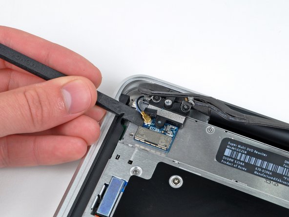
Disconnect the Bluetooth cable by pulling the male end straight away from its socket.
-
Use the flat end of a spudger to carefully pry the AirPort antenna off its socket on the AirPort card.
-
-
Este passo não foi traduzido. Ajude a traduzi-lo
-
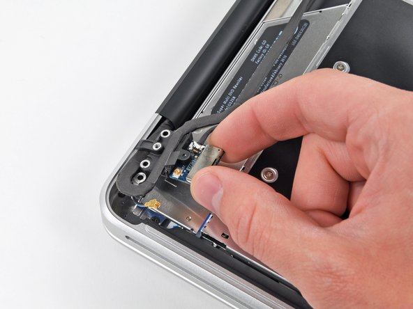
Remove the two 8 mm Phillips screws securing the Bluetooth/camera cable retainer to the upper case.
-
Lift the AirPort board/cable retainer assembly out of the upper case.
-
-
Este passo não foi traduzido. Ajude a traduzi-lo
-
Remove the single 3.5 mm Phillips screw securing the inner side of the optical drive to the upper case.
-
-
Este passo não foi traduzido. Ajude a traduzi-lo
-
Remove the two 3.5 mm Phillips screws securing the outer side of the optical drive to the upper case.
-
-
Este passo não foi traduzido. Ajude a traduzi-lo
-
Lift the optical drive from its left edge and pull it out of the upper case.
-
-
Este passo não foi traduzido. Ajude a traduzi-lo
-
Remove the following four screws securing the subwoofer and right speaker assembly to the upper case:
-
Two 3.2 mm Phillips screws.
-
One 2.6 mm Phillips screw.
-
One 5 mm Phillips screw.
-
-
Este passo não foi traduzido. Ajude a traduzi-lo
-
Lift the subwoofer and right speaker assembly out of the upper case.
-
-
Este passo não foi traduzido. Ajude a traduzi-lo
-
Remove the two 8 mm Phillips screws securing the camera cable retainer to the upper case.
-
Lift the camera cable retainer out of the upper case.
-
-
Este passo não foi traduzido. Ajude a traduzi-lo
-
Remove the outer two T6 Torx screws securing both display hinges to the upper case (four screws total).
-
-
Este passo não foi traduzido. Ajude a traduzi-lo
-
Open your MacBook Pro so the display is perpendicular to the upper case.
-
Place your opened MacBook Pro on a table as pictured.
-
While holding the display and upper case together with your left hand, remove the remaining T6 Torx screw from the lower display bracket.
-
-
Este passo não foi traduzido. Ajude a traduzi-lo
-
Remove the last remaining 6 mm Torx screw securing the display to the upper case.
-
-
Este passo não foi traduzido. Ajude a traduzi-lo
-
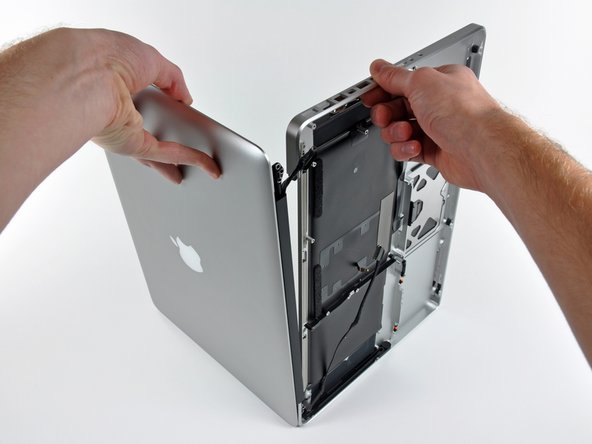
Grab the upper case with your right hand and rotate it slightly toward the top of the display so the upper display bracket clears the edge of the upper case.
-
Rotate the display slightly away from the upper case.
-
Lift the display away from the upper case, minding any brackets or cables that may get caught.
-


Cancelar: não concluí este guia.
36 outras pessoas executaram este guia.

Um comentário
Thanks for a fantastic guide! I needed to replace my track pad and this served me well. Also was the perfect opportunity to clean out all the dust. A couple minor mods and a trackpad guide could be published for all those like me.
Cheers!