Esta versão pode conter edições incorretas. Mude para o último instantâneo verificado.
O que você precisa
-
Este passo não foi traduzido. Ajude a traduzi-lo
-
The bottom cover is clipped onto three screw posts.
-
Pry near, but not right on the screw posts.
-
-
Este passo não foi traduzido. Ajude a traduzi-lo
-
Use the plastic opening tool to pry the bottom cover up off of the Mac mini.
-
-
Este passo não foi traduzido. Ajude a traduzi-lo
-
Remove the following TR6 screws from the antenna plate:
-
Three 4.1 mm screws
-
Three 1.9 mm screws
-
-
Este passo não foi traduzido. Ajude a traduzi-lo
-
With the I/O ports facing you, flip the antenna plate to the right to allow access to the antenna cable connector.
-
-
Este passo não foi traduzido. Ajude a traduzi-lo
-
Remove the single 3.4 mm T6 screw and washer from the antenna cable.
-
-
Este passo não foi traduzido. Ajude a traduzi-lo
-
Use the point of a spudger to lift the antenna connector straight up off its socket on the airport card.
-
-
Este passo não foi traduzido. Ajude a traduzi-lo
-
Carefully pull the antenna cable out from the gap between the power supply and case.
-
-
Este passo não foi traduzido. Ajude a traduzi-lo
-
Remove the two 12 mm T6 screws from the fan.
-
Loosen the 27 mm T6 captive screw–it will get removed with the fan assembly.
-
-
Este passo não foi traduzido. Ajude a traduzi-lo
-
Lift the fan straight up to free the captive screw from its hole in the logic board.
-
Pull the fan away from the SSD until you can easily access the fan connector.
-
-
Este passo não foi traduzido. Ajude a traduzi-lo
-
Use the point of a spudger to lift the fan connector straight up out of its socket on the logic board.
-
-
-
Este passo não foi traduzido. Ajude a traduzi-lo
-
Remove the 2.6 mm T6 screw securing the SATA cable connector bracket.
-
-
Este passo não foi traduzido. Ajude a traduzi-lo
-
Use the flat end of a spudger to lift the SATA cable connector up off of its socket on the logic board.
-
-
Este passo não foi traduzido. Ajude a traduzi-lo
-
Use the tip of a spudger to disconnect the IR sensor cable connector by prying it straight up from its socket.
-
-
Este passo não foi traduzido. Ajude a traduzi-lo
-
The following three steps only apply to Mac minis equipped with a PCIe SSD. Skip the next three steps if your Mac mini only has a hard drive.
-
Remove the two 2.6 mm T6 screws securing the PCIe SSD cable bracket.
-
-
Este passo não foi traduzido. Ajude a traduzi-lo
-
Remove the single 16 mm T6 screw securing the logic board.
-
-
Este passo não foi traduzido. Ajude a traduzi-lo
-
Insert the Mac mini Logic Board Removal Tool into the two holes highlighted in red. Be sure the rods make contact with the case under the logic board before proceeding.
-
-
Este passo não foi traduzido. Ajude a traduzi-lo
-
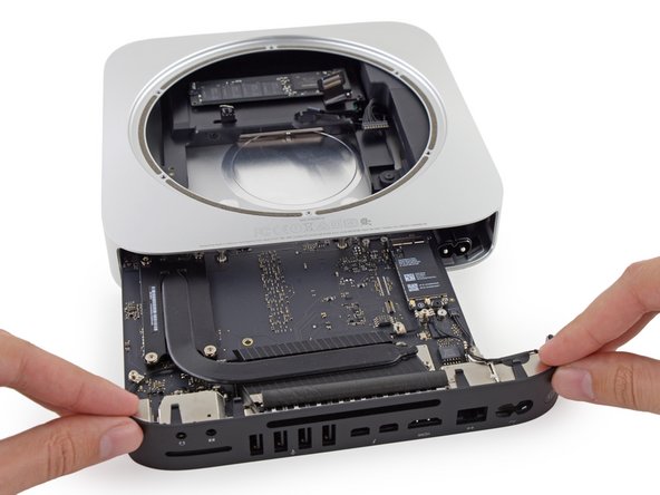
Carefully pull the tool toward the I/O board. The logic board and I/O board assembly should slightly slide out of the outer case.
-
Cease prying when the removal tool makes contact with the opening in the rear case.
-
-
Este passo não foi traduzido. Ajude a traduzi-lo
-
Pull the DC-In cable connector straight out of its socket on the logic board.
-
-
Este passo não foi traduzido. Ajude a traduzi-lo
-
Carefully slide the logic board assembly out of the Mac mini, minding any cables that may get caught.
-
-
Este passo não foi traduzido. Ajude a traduzi-lo
-
Remove the following screws securing the heat sink to the logic board:
-
Four 8.6 mm T8 Torx screws
-
One 2.9 mm T6 Torx screw
-
-
Este passo não foi traduzido. Ajude a traduzi-lo
-
Remove the following T6 Torx screws from the I/O port antenna cables:
-
Three 2.8 mm screws with washers
-
One 3.4 mm screw
-
One 2.7 mm screw
-
-
Este passo não foi traduzido. Ajude a traduzi-lo
-
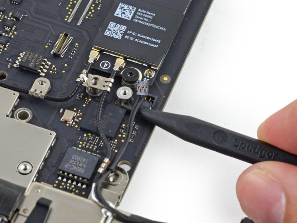
Use the point of a spudger to lift the power switch cable connector straight up out of its socket on the logic board.
-
-
Este passo não foi traduzido. Ajude a traduzi-lo
-
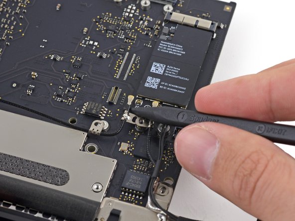
Use the point of a spudger to lift the antenna connectors up off of their sockets on the AirPort card.
-
-
Este passo não foi traduzido. Ajude a traduzi-lo
-
Remove the four 2.7 mm T6 Torx screws holding the I/O bezel to the logic board.
-
-
Este passo não foi traduzido. Ajude a traduzi-lo
-
Remove the foam bumper from between the I/O bezel and USB ports.
-
-
Este passo não foi traduzido. Ajude a traduzi-lo
-
Pull the I/O bezel off of the logic board, minding any cables that may get caught.
-
-
Este passo não foi traduzido. Ajude a traduzi-lo
-
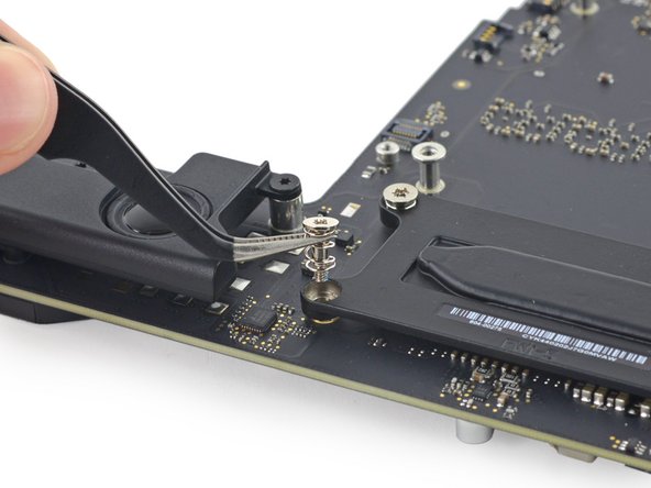
Remove the following T6 Torx screws securing the speaker to the logic board:
-
One 3.6 mm screw
-
One 3.6 mm large headed screw
-
-
Este passo não foi traduzido. Ajude a traduzi-lo
-
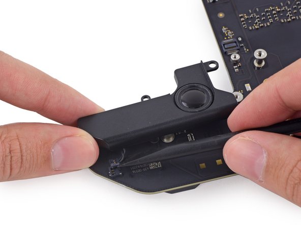
Nudge the speaker gently out of the way to allow access to the speaker's connector.
-
-
Este passo não foi traduzido. Ajude a traduzi-lo
-
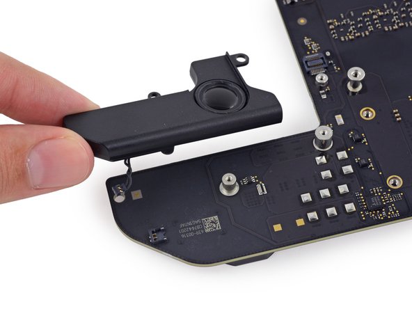
Use the flat end of a spudger to carefully lift the speaker connector up out of its socket on the logic board.
-
Remove the speaker from the logic board.
-
-
Este passo não foi traduzido. Ajude a traduzi-lo
-
Remove the 2.7 mm T5 screw securing the AirPort card.
-
-
Este passo não foi traduzido. Ajude a traduzi-lo
-
Lift the free end of the AirPort card enough to grasp it by the edges.
-
Pull the AirPort card straight out of its socket on the logic board and remove it from the Mac Mini.
-


Cancelar: não concluí este guia.
16 outras pessoas executaram este guia.


4 comentários
is there any internal battery on the logic board..
It is called a hard drive tray or hard drive carrier. You can find the guide to remove it here.