Introdução
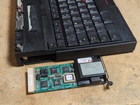
Need to repair an IBM Thinkpad 700C? Then this guide is for you. It uses lots of photos and thoroughly documents the sizes and types of screws used in each subassembly. This is particularly useful because the official service manual is full of errors.
O que você precisa
-
-
Screw sizes in this guide are given in millimeters. This is the length of the threads alone, not the head.
-
Actual screws are slightly shorter than the nominal length.
-
All the machine screws are M2.5 Phillips head unless otherwise noted.
-
-
-
Open the laptop screen almost all the way.
-
Set the laptop on its side.
-
Using a spudger, unhook the LED cover's plastic tabs on the back of the laptop base.
-
From the front of the laptop, pivot the LED indicator cover towards the keyboard and unhook the tabs on this side.
-
-
-
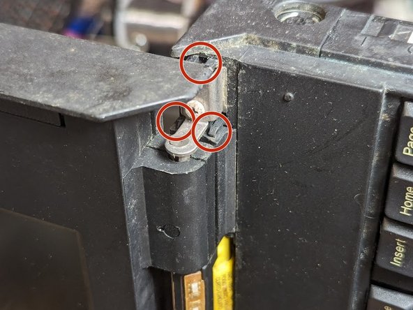
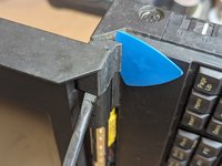
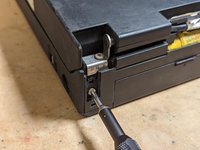
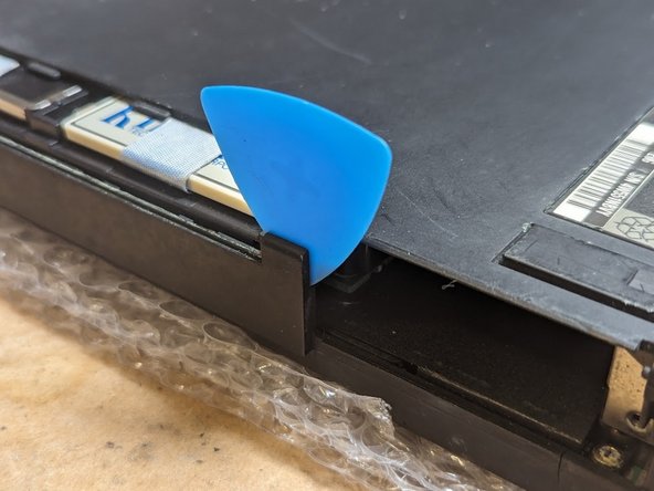
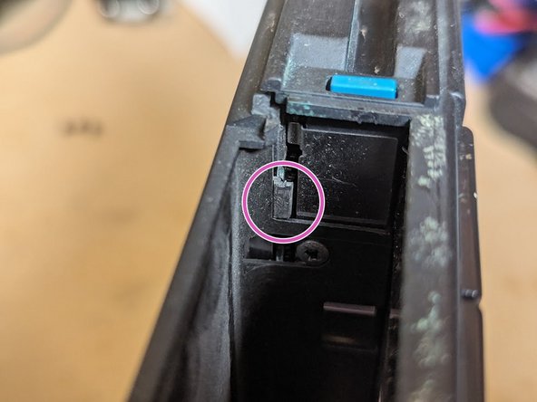
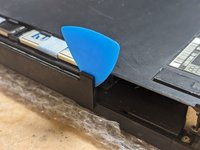
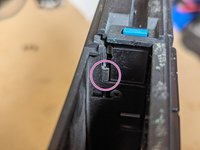
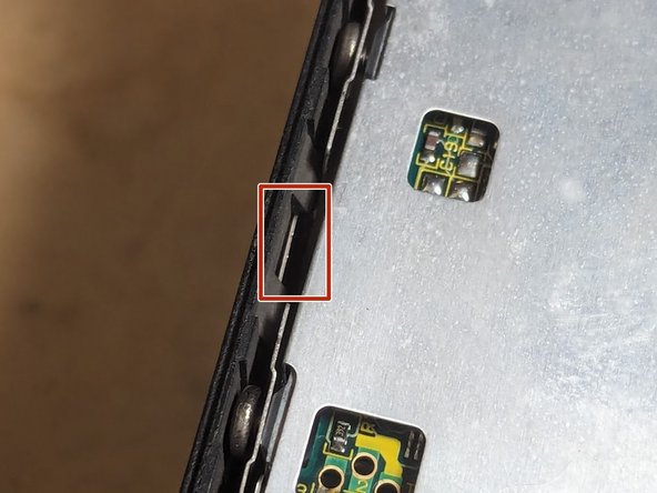
Remove the hinge covers on each end of the laptop using a guitar pick and a spudger tool.
-
There are three plastic latches you are trying to release. They are circled in red.
-
You may need to adjust the spudger and guitar pick position to release all the latches.
-
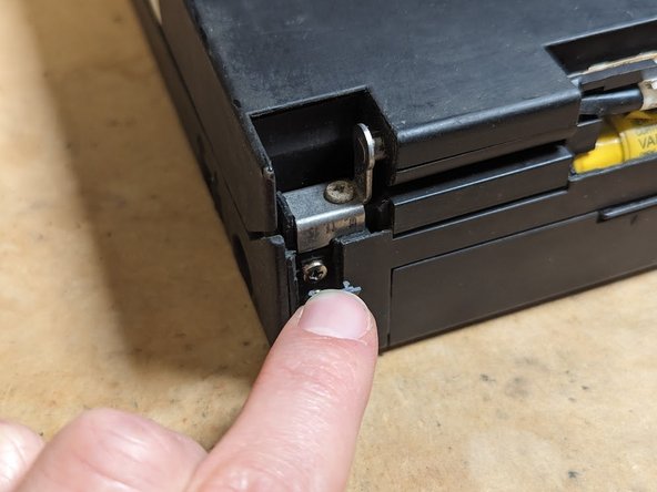
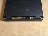
Repeat for the hinge cover on the opposite side.
-
-
-
Gently close the laptop. Use guitar picks or something to prop the front of the screen so the two latches don't engage.
-
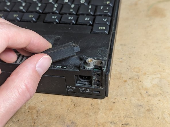
Using your fingernail or a spudger, remove the two screw covers from the top.
-
Remove the four 3mm screws on the rear surface of the laptop securing the LCD hinge.
-
Remove the two 5mm screws holding the top of the hinge to the base of the laptop.
-
-
-
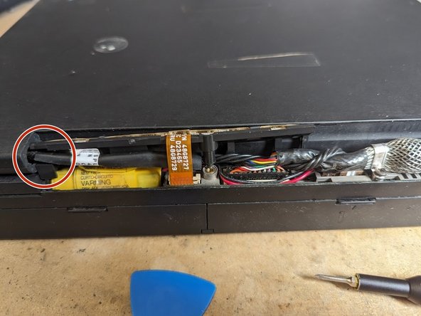
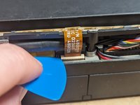
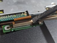
Unlatch the flex connector with a guitar pick or your fingernail, then gently pull the flex cable free.
-
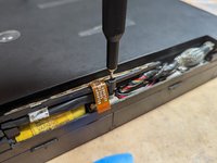
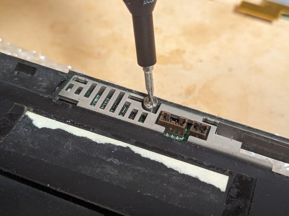
Using a small PH00 Phillips bit from your screwdriver kit, loosen the screw holding the LED assembly in place.
-
Pull the LED indicator board free, unhooking it from the 4-wire cable (LCD backlight power)
-
-
-
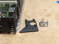
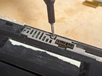
Remove the 3mm screw holding the LCD data cable bracket in place.
-
Unplug the 4-pin LCD backlight power cable and the multicolor LCD data cable using a spudger.
-
-
-
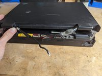
Gently lift the laptop screen up, allowing the hinges to slide clear from the base, and set it aside.
-
Remove the two plastic hinge spacers resting on the laptop base.
-
-
-
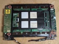
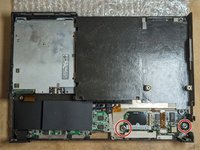
Using a dental pick or small screwdriver, remove the two rubber plugs (blue circles)
-
With the dental pick or screwdriver, remove the two rubber disks (red circles) that cover up the screws.
-
Using a T6 Torx driver, remove the four 5mm screws formerly covered by the plugs and disks.
-
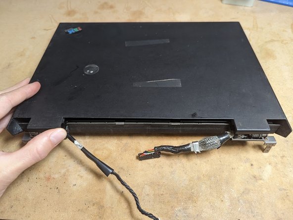
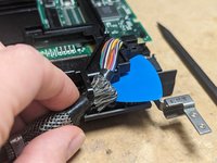
Flip the panel over face down, then lift up the back cover on the hinge side.
-
Slide the back cover forward to clear the lid latch hooks in the two front corners.
-
The cover should lift right off.
-
-
-
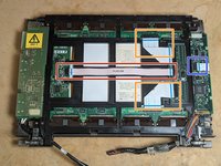
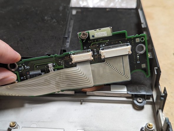
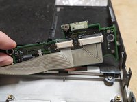
Remove the long flex cable (red box)
-
Remove the two 90 degree flex cables (orange boxes), again being sure to record their exact orientation and location.
-
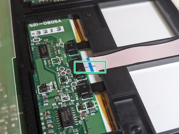
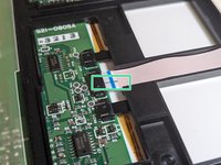
Disconnect the flex cable on the far right (blue box).
-
-
-
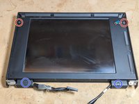
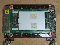
Remove the four 12mm screws in each corner of the panel (red circles)
-
Prop the corner of the frame up with a guitar pick and unhook the data cable, flipping it up on top of the frame.
-
Repeat for the LCD backlight power cable.
-
Lift the frame stiffener up and off the LCD panel.
-
-
-
Remove the four 6mm self-tapping screws securing both circuit boards.
-
Lift up and remove the LCD driver board (right).
-
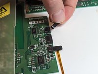
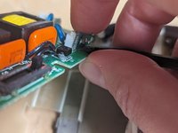
Unplug the two small flex cables from the backlight board, being sure to properly unlatch the connectors first.
-
Flip the backlight power board over to the left, exposing the CCFL high voltage wires.
-
Disconnect the two CCFL high voltage wires.
-
-
-
-
While you have the CCFL board out, you will likely want to replace the leaky electrolytic capacitors.
-
C1: 220uF 35V radial leaded electrolytic, 10mm tall, 10.1mm dia. lead spacing 5mm. Mouser p/n: 581-REF1009221M035K
-
C2: 4.7uF 25V radial leaded electrolytic, 5.7mm tall, 4.1mm dia lead spacing 2mm. Mouser p/n: 667-ECE-A1EKS4R7I
-
C3: 33uF 6.3V radial leaded electrolytic, 5.7mm tall, 5.1mm dia lead spacing 2.5mm. Mouser p/n: 667-ECE-A1CKS330
-
-
-
Likewise, the LCD driver board typically needs capacitors replaced.
-
C1, C2: 22uF 35V SMD electrolytic 5.6mm tall, 6.25mm dia. Mouser p/n 667-EEE-HB1V220P
-
C3, C4: 47uF 25V SMD electrolytic 6.4mm tall, 8mm dia. Mouser p/n 667-EEE-HB1E470AP
-
C5: 100uF 16V SMD electrolytic 6.4mm tall, 8mm dia. Mouser p/n 667-EEE-HBE101UAP
-
Electrolyte leakage from the old capacitors may also damage the trimmer resistors. Both original parts are Panasonic EVM1U which is no longer available. You may be able to bodge wire modern trimmers.
-
R1: 20K ohm, typically set with the upper resistance at 6K and the lower resistance at 14K (metal cup side up, 3 leads to the right, 1 lead to the left.) Probably safe to replace them with individual resistors.
-
R2: 500 ohms set to the halfway point (250 ohms from center to each side)
-
-
-
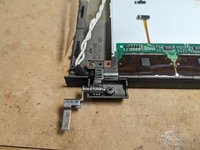
Take out the two 8mm screws fastening the hinges in place.
-
Remove the hinges. They are not identical so keep track of which is which.
-
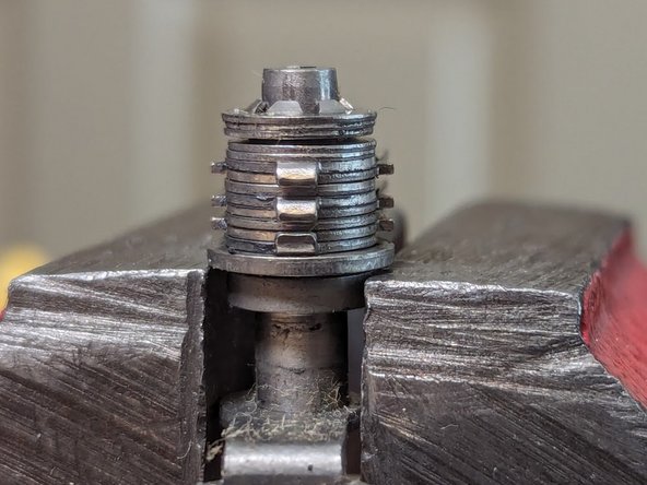
Place the hinge in a vice but do not tighten it down.
-
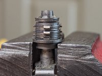
Rest the hinge on the bottom sheet metal without gripping the metal pin. The locking washer should be facing upwards.
-
Tap the top of the metal pin with a hammer to loosen up the hinge action.
-
If you loosen the hinge too much, take it out of the vice and place it on top of the vice. put a small hex driver over the top and tap it with a hammer to drive the locking washer back down.
-
-
-
Lift the plastic CCFL and diffuser assembly straight up and away. The upper and lower driver boards will need to be flex back and out of the way.
-
-
-
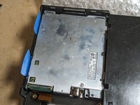
Remove the battery by sliding the battery faceplate down then pulling the battery forward, out of the unit.
-
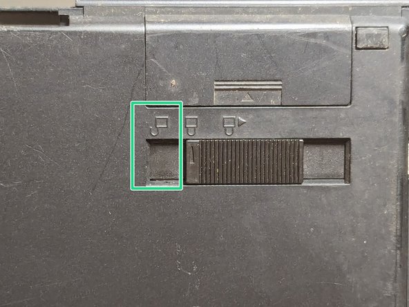
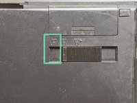
Set the hard drive cover switch to the unlocked position
-
Slide the hard drive cover forward, away from the unit.
-
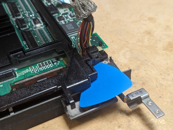
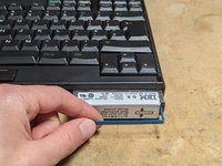
With a fingernail, snag the blue bar on the front of the hard drive. Pull on it and the hard drive should disconnect and slide free.
-
-
-
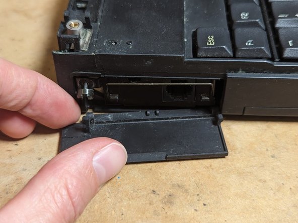
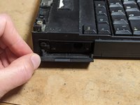
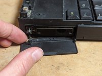
Tilt the modem cover down.
-
Loosen the screw holding the modem in place with a flat screwdriver. It is a captive screw so it will not come out all the way.
-
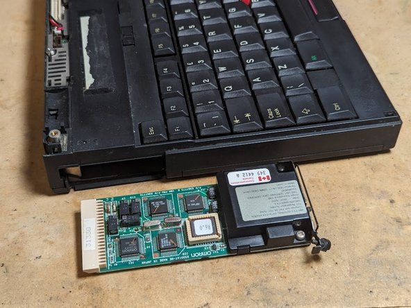
Remove the modem cover by pulling forward from the left edge, and then pull it to the left to disengage it from the right hinge pin.
-
Snag the pull handle (wire) with a fingernail and pull the modem free of the unit.
-
-
-
Unplug the standby battery connector with a spudger.
-
The standby battery is not otherwise held in place and should drop right out.
-
-
-
Flip the laptop over and place it on several layers of bubble wrap to protect the fragile plastic hooks that retain the LED indicator cover and hinge covers.
-
Remove the memory cover by pushing it down and to the left.
-
You may need to use a guitar pick to give it a little encouragement.
-
-
-
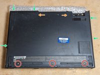
Remove three black 4mm screws.
-
Use guitar picks to dislodge 5 plastic latches around the perimeter (arrows)
-
There are two hidden plastic latches (arrows), one inside the hard drive slot, and the other between the floppy drive and the battery slot.
-
You may need to use a combination of a guitar pick and a spudger to dislodge the latch in the battery slot.
-
Remove the cover and set it aside.
-
-
-
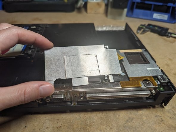
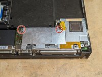
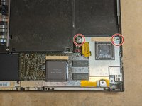
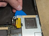
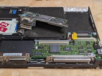
Remove two silver 5mm screws from the upper part of the video card shield.
-
Tilt the shield forward and slide it backwards to remove it.
-
-
-
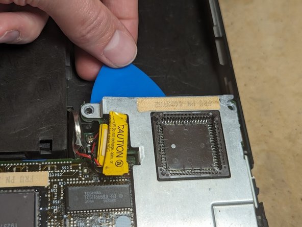
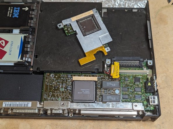
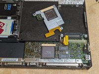
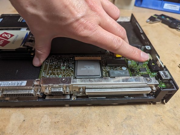
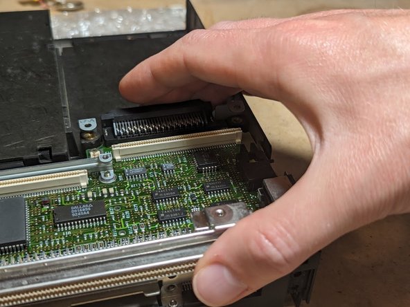
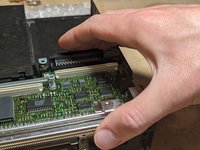
Remove two silver 5mm screws from the CPU card.
-
Use a guitar pick to help pry the CPU card up and out of its connector, which is directly beneath the area with the screws.
-
-
-
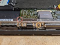
Remove the black 4mm screw above the parallel port.
-
Remove the silver 4mm screw from between the docking port and the VGA connector.
-
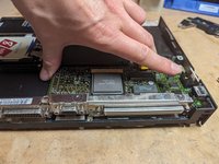
Pull straight up from the top left and right of the video card to unplug it from the planar (motherboard).
-
-
-
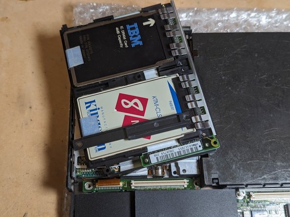
Remove the two 16mm screws from the memory card.
-
Unplug the memory board from the planar and lift it away.
-
-
-
Push in on the plastic piece on the outside of the case next to the PS/2 mouse connector.
-
While maintaining pressure, slide the plastic part up to release the plastic latches. The part should come away.
-
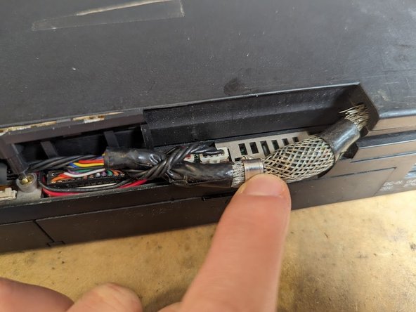
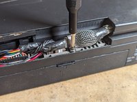
Gently pull off the metal connector shield.
-
Lift the power switch slider up and away from the case.
-
Remove the coin cell using a spudger on its connector.
-
-
-
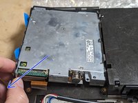
Unlatch the floppy drive flex cable using a spudger.
-
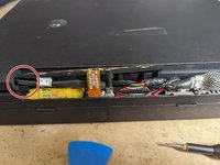
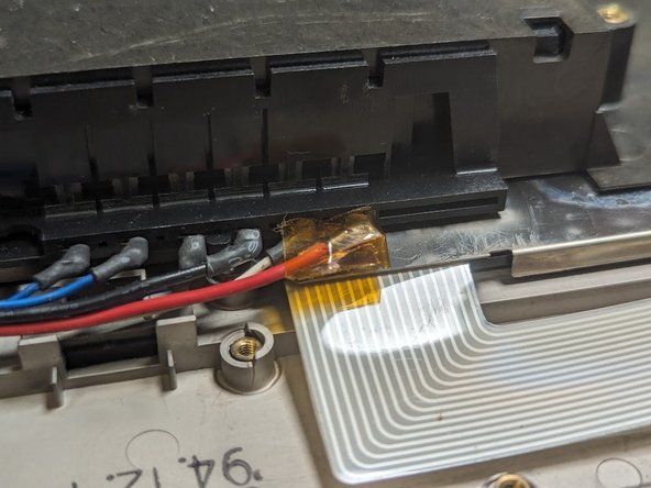
Flip the laptop over and remove the slotted standoff next to the 4-pin LCD backlight power connector
-
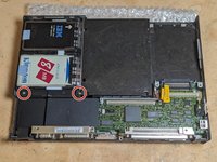
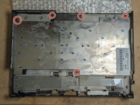
Flip the laptop back over and remove the five 4mm screws holding the planar to the case.
-
-
-
Hold the thin plastic modem cover out of the way and, with your fingers, gently pry up the left edge of the planar.
-
Gently pull up on the right side of the planar.
-
-
-
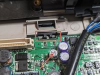
Unscrew the black 8mm screw holding the battery holder clip in place. Remove both the screw and the clip
-
Remove the two silver 5mm screws on either side of the AC adapter power jack cover.
-
Remove the AC adapter power jack cover itself.
-
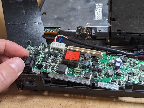
Lift out the power board and unplug it from the battery connector.
-
-
-
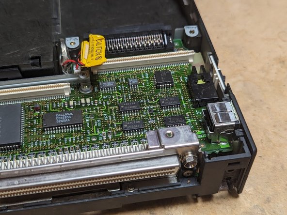
Remove the two black 3mm screws on the left and right sides of the board
-
Unplug the amber flex cable going to the trackpoint using a spudger.
-
Flip the board up and disconnect the two keyboard flex cables.
-
-
-
Insert two guitar picks into the metal latches on the left side of the floppy drive. They should go between the metal tab (red box) and the plastic case.
-
Tilt up the left side of the floppy drive.
-
Pull the floppy drive diagonally to disengage the right side from the frame stiffener.
-
-
-
Remove the frame stiffener by unscrewing the six black 3mm-long screws.
-
-
-
Remove the five black 3mm screws from the keyboard and the trackpoint button stiffener plate.
-
Remove the trackpoint button stiffener plate
-
Remove the keyboard.
-


To reassemble your device, follow these instructions in reverse order.
To reassemble your device, follow these instructions in reverse order.
Cancelar: não concluí este guia.
Uma outra pessoa concluiu este guia.