Esta versão pode conter edições incorretas. Mude para o último instantâneo verificado.
O que você precisa
-
Este passo não foi traduzido. Ajude a traduzi-lo
-
Insert a SIM eject tool, SIM eject bit, or a paperclip into the small hole on the left edge of the phone, near the top.
-
Press to eject the tray.
-
-
Este passo não foi traduzido. Ajude a traduzi-lo
-
Heat an iOpener and apply it to the top edge of the display for two minutes.
-
Take note of the following regions before you begin prying:
-
Thin adhesive lined against the display panel
-
Thick adhesive
-
The OLED display panel, which is very prone to damage
-
The display cable, which can be damaged during prying
-
-
Este passo não foi traduzido. Ajude a traduzi-lo
-
Once the edge is warm to the touch, apply a suction cup close to the edge.
-
Lift on the suction cup, and insert an opening pick into the gap.
-
If you have trouble creating a gap, reheat the edge and try again.
-
-
Este passo não foi traduzido. Ajude a traduzi-lo
-
Slide the opening clip across the top edge to slice through the adhesive.
-
Leave an opening pick in the edge to prevent the adhesive from resealing.
-
-
Este passo não foi traduzido. Ajude a traduzi-lo
-
Heat an iOpener and apply it to the right edge of the phone for two minutes.
-
Insert an opening pick near the top edge of the phone, where you have already sliced the adhesive.
-
Slowly guide the pick around the right corner.
-
Carefully slide the pick down the right edge of the phone to slice through the adhesive.
-
Repeat the step for the left edge of the phone.
-
-
Este passo não foi traduzido. Ajude a traduzi-lo
-
Heat the bottom edge with an iOpener for two minutes.
-
Insert a pick near the right edge where you have already loosened the adhesive.
-
Carefully guide the pick around the corner.
-
Slide the pick along the bottom edge to slice through the adhesive.
-
-
Este passo não foi traduzido. Ajude a traduzi-lo
-
Once you have sliced around the perimeter of the phone, carefully lift the display assembly up slightly by the right corners.
-
Use an opening pick to slice through any remaining adhesive.
-
-
Este passo não foi traduzido. Ajude a traduzi-lo
-
Lift the display assembly from the top end and swing it around such that it rests upside down on the frame.
-
-
Este passo não foi traduzido. Ajude a traduzi-lo
-
Remove the two 4 mm T5 screws securing the display cable bracket.
-
Remove the display cable bracket.
-
-
Este passo não foi traduzido. Ajude a traduzi-lo
-
Use the point of a spudger to pry up and disconnect the display cable from its connector.
-
-
-
Este passo não foi traduzido. Ajude a traduzi-lo
-
Remove the following screws that secure the midframe to the back:
-
Seven black 4 mm T5 screws
-
Two silver 3 mm T5 screws
-
-
Este passo não foi traduzido. Ajude a traduzi-lo
-
The midframe is held tightly in place by plastic clips which push into the edge of the back case.
-
-
Este passo não foi traduzido. Ajude a traduzi-lo
-
Find the small notch in the bottom left corner of the frame and insert an opening pick.
-
Slide the opening pick along the bottom edge of the phone towards the bottom right corner and leave it there.
-
-
Este passo não foi traduzido. Ajude a traduzi-lo
-
Insert a separate opening pick into the right edge of the phone, near the bottom.
-
Slowly push the pick upwards along the seam until the first clip pops free.
-
Once you've released the clip, leave the opening pick in place to prevent the midframe from resealing.
-
-
Este passo não foi traduzido. Ajude a traduzi-lo
-
Insert an opening pick into the right edge of the phone and slide it upwards towards the top right clip.
-
Slowly slide the pick past the clip to disengage it from the frame.
-
-
Este passo não foi traduzido. Ajude a traduzi-lo
-
Grasp the right edge of the midframe by the corners and slowly hinge the edge up.
-
When the left edge feels loose, stop hinging and lift the midframe upwards.
-
Remove the midframe.
-
-
Este passo não foi traduzido. Ajude a traduzi-lo
-
Use the point of a spudger to pry up and disconnect the battery connector.
-
Bend the battery flex cable slightly so that it will not accidentally touch the motherboard.
-
-
Este passo não foi traduzido. Ajude a traduzi-lo
-
Use the point of a spudger to pry up and disconnect the button strip connector.
-
-
Este passo não foi traduzido. Ajude a traduzi-lo
-
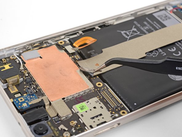
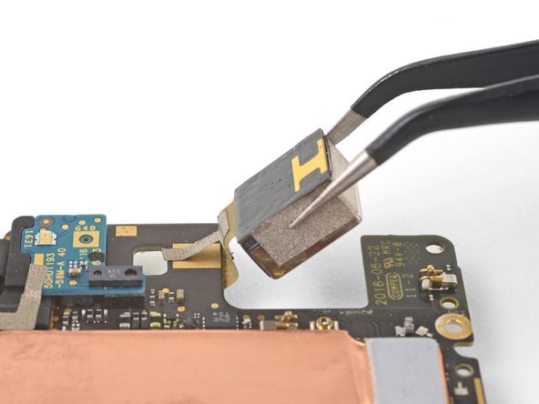
Use tweezers to peel up the tape at the top of the interconnect cable.
-
-
Este passo não foi traduzido. Ajude a traduzi-lo
-
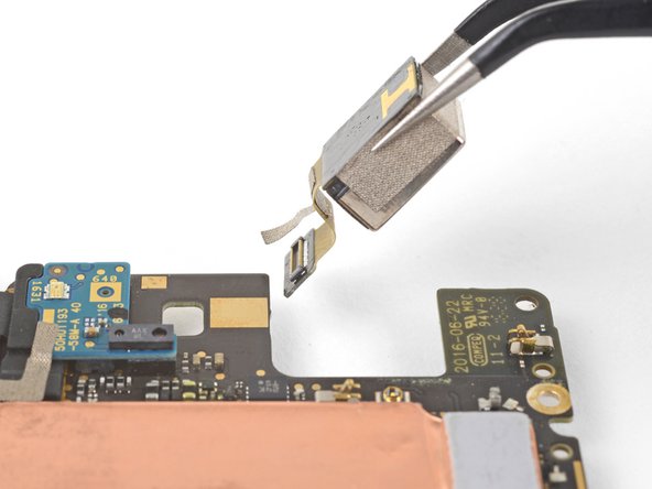
Use the point of a spudger to pry up and disconnect the interconnect cable from the motherboard.
-
-
Este passo não foi traduzido. Ajude a traduzi-lo
-
Use the point of a spudger to disconnect the black antenna cable from the motherboard, near the front facing camera module.
-
Route the antenna cable out of its retaining clip.
-
-
Este passo não foi traduzido. Ajude a traduzi-lo
-
Use the point of a spudger to pry up and disconnect the white antenna cable from the motherboard, near the rear facing camera module.
-
Route the antenna cable out of its retaining clip.
-
-
Este passo não foi traduzido. Ajude a traduzi-lo
-
Remove the two 3 mm T5 screws securing the motherboard to the frame.
-
-
Este passo não foi traduzido. Ajude a traduzi-lo
-
Use the point of a spudger to pry up and loosen the front facing camera module from its socket.
-
-
Este passo não foi traduzido. Ajude a traduzi-lo
-
Insert the point of a spudger into the headphone jack port and pry upwards to loosen the port from its socket.
-
-
Este passo não foi traduzido. Ajude a traduzi-lo
-
Use the flat end of a spudger to pry the bottom edge of the motherboard up slightly, loosening it from its recess.
-
-
Este passo não foi traduzido. Ajude a traduzi-lo
-
Locate the fingerprint sensor cable attached to the underside of the motherboard, near the bottom edge.
-
Use the point of a spudger to pry and release the fingerprint sensor cable from its socket.
-
Peel the cable away from the motherboard.
-
-
Este passo não foi traduzido. Ajude a traduzi-lo
-
Hold the motherboard by the corners and maneuver it out of its recess, being careful not to snag any cables.
-
Bend the fingerprint sensor cable slightly so that it bows upward near the connector.
-
Stand the motherboard up and position it such that the connector rests against the socket.
-
Use your finger to carefully align the connector and press it into the socket. Do not use excessive force! If done correctly, the socket should hold the connector securely.
-
-
Este passo não foi traduzido. Ajude a traduzi-lo
-
Flip the motherboard such that the underside is facing up.
-
Use the point of a spudger to pry up and disconnect the rear facing camera connector from its socket.
-
-
Este passo não foi traduzido. Ajude a traduzi-lo
-
Flip the motherboard such that the backside is facing down.
-
Pivot the camera module out of its recess and slowly pull it out, lifting the adhesive tape in the process.
-
Remove the rear camera module.
-


Cancelar: não concluí este guia.
6 outras pessoas executaram este guia.


5 comentários
https://www.witrigs.com/oem-rear-camera-...
This is one of other only places I could find to get a replacement camera module.
iFixit sells the replacement part here. It looks like new camera modules are out of stock, but used and fully tested ones are still in stock as of May 15, 2018.
A helpful tip: before you re-assemble the phone, shine a bright light through the back glass and check that there is no dust or debris on the inside of the back glass or the camera lens.
Also, this may be obvious to some, but you will need replacement adhesive for the display in order to re-attach it to the phone. I didn’t even think about this until I had already started the repair and taken the display off.
Do you think that if I put a Pixel 3 camera in there, it would still work?
Have any of you tried to up the storage capacity on one of these things?