Esta versão pode conter edições incorretas. Mude para o último instantâneo verificado.
O que você precisa
-
Este passo não foi traduzido. Ajude a traduzi-lo
-
Insert a SIM eject tool, bit, or straightened paper clip into the SIM tray hole.
-
Press directly into the hole to eject the SIM card tray.
-
Remove the SIM card tray.
-
-
-
Observe as duas costuras na borda do telefone:
-
Emenda da tela: esta emenda separa a tela do resto do fone. É aqui que você deve fazer alavanca.
-
Emenda da moldura: é aqui que a moldura de plástico e a tampa traseira se tocam. Ela é fixada por meio de parafusos. Não faça alavanca nesta emenda.
-
Antes de começar, observe as seguintes áreas da tela:
-
Cabo conector flex da tela: não insira a palheta de abertura a uma profundidade maior do que a instruída ou você corre o risco de danificar esse cabo.
-
Limite do adesivo: fazer alavanca além deste limite estrito sem inclinar a palheta causará danos ao painel OLED.
-
-
-
Aplique uma bolsa térmica iOpener aquecida na borda direita do visor por um minuto para amolecer o adesivo.
-
-
-
Coloque uma ventosa de sucção o mais próximo possível da borda direita da tela.
-
Levante a ventosa com força e firmeza.
-
Insira a ponta de uma palheta de abertura na emenda da tela sem exceder 1 mm.
-
-
-
Com a palheta inserida 1 mm no vão, vire a palheta para cima, para deixá-la em um ângulo menor em relação ao fone.
-
Perfazendo um ângulo obtuso em relação ao fone, empurre cuidadosamente a palheta no vão por uns 6 mm ou 1/4 de polegada. A palheta deve deslizar para dentro abaixo do painel OLED.
-
-
-
Passe a palheta ao longo da borda direita da tela para cortar o adesivo.
-
Deixe a palheta no canto superior direito para evitar que o adesivo volte a selar.
-
-
-
Insira outra palheta de abertura inclinada onde já tenha se formado um vão na borda direita do telefone, para evitar danos ao painel OLED.
-
Deslize a palheta de abertura ao redor da parte inferior do telefone para cortar o adesivo.
-
Deixe a palheta inserida na borda inferior para evitar que o adesivo volte a selar.
-
-
-
Insira outra palheta de abertura inclinada onde já tenha se formado um vão na borda inferior do telefone, para evitar danos ao painel OLED.
-
Use a palheta para abrir caminho pela borda esquerda do telefone.
-
Deixe a palheta inserida na borda esquerda do telefone para evitar que o adesivo volte a selar.
-
-
-
Levante a tela pela borda superior e vire-a por sobre a borda inferior, até que possa apoiá-la com o lado do vidro para baixo.
-
-
-
-
Com uma pinça, retire cuidadosamente a fita preta que cobre o suporte do conector da tela.
-
-
-
Remova a tela.
-
Compare a tela de reposição com a original. Pode ser que você precise transferir componentes adicionais (como a grelha do alto-falante) para a peça nova.
-
Raspe o adesivo restante do contorno da moldura.
-
Siga este guia se você estiver usando adesivos customizados.
-
Se você estiver usando uma fita dupla face como a fita da Tesa, siga este guia.
-
-
Este passo não foi traduzido. Ajude a traduzi-lo
-
Use a T3 Torx driver to remove the eight 4.3 mm screws securing the back cover to the midframe.
-
-
Este passo não foi traduzido. Ajude a traduzi-lo
-
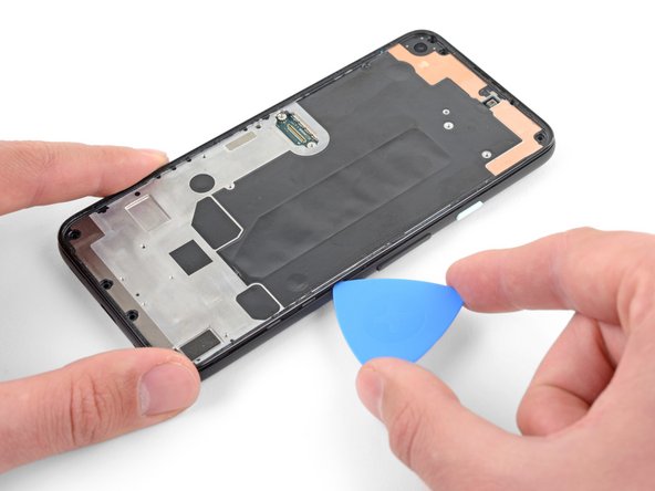
Insert an opening pick into the seam between the midframe and the back cover.
-
Slide the opening pick along the bottom edge of the phone to release the plastic clips securing the back cover to the midframe.
-
-
Este passo não foi traduzido. Ajude a traduzi-lo
-
Slide the opening pick around the left edge of the phone to release the plastic clips securing the back cover to the midframe.
-
-
Este passo não foi traduzido. Ajude a traduzi-lo
-
Slide the opening pick around the top and right edges of the phone to release the rest of the clips.
-
-
Este passo não foi traduzido. Ajude a traduzi-lo
-
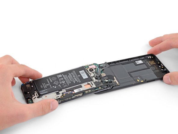
Carefully swing the back cover from the bottom of the phone over the top and around the back.
-
Lay the back cover on the work surface and lightly rest the midframe on the back cover, being careful not to put any stress on the attached ribbon cables.
-
-
Este passo não foi traduzido. Ajude a traduzi-lo
-
Use a T3 Torx driver to remove the seven screws securing the motherboard bracket:
-
Three 2.9 mm-long black screws
-
Three 2 mm-long screws
-
One 4.1 mm-long screw
-
-
Este passo não foi traduzido. Ajude a traduzi-lo
-
Use the tip of a spudger to unclip the motherboard bracket from the upper-right and lower-right corners of the motherboard.
-
-
Este passo não foi traduzido. Ajude a traduzi-lo
-
Use a pair of tweezers to remove the motherboard bracket.
-
-
Este passo não foi traduzido. Ajude a traduzi-lo
-
Use the flat end of a spudger to pry up and disconnect the battery cable.
-
-
Este passo não foi traduzido. Ajude a traduzi-lo
-
Use the tip of a spudger to disconnect the two flex cables connecting the fingerprint sensor and buttons to the motherboard.
-
-
Este passo não foi traduzido. Ajude a traduzi-lo
-
Use a T3 Torx driver to remove the two 4.1 mm screws securing the loudspeaker assembly.
-
-
Este passo não foi traduzido. Ajude a traduzi-lo
-
Insert the tip of a spudger underneath the loudspeaker assembly.
-
Flip the loudspeaker assembly over so it lightly rests on top of the battery.
-
-
Este passo não foi traduzido. Ajude a traduzi-lo
-
Use the tip of a spudger to disconnect the antenna flex cable from the loudspeaker assembly.
-
-
Este passo não foi traduzido. Ajude a traduzi-lo
-
Carefully peel the loudspeaker assembly up off of the tape underneath it.
-
Remove the loudspeaker assembly.
-


Cancelar: não concluí este guia.
Uma outra pessoa concluiu este guia.
