No Display But Backlight Works. Microsoldering Question.
Hello.
I am working on an iPad 7 (2019) that came in for no display. Customer said the screen flashed green and then afterwards only the backlight was visible on the display. No image. The iPad is booting, as you can hear notification sounds and Siri.
I started by simply disassembling the iPad, disconnect the LCD flex cable, clean the connector, and reconnect. Same behavior. Backlight works, no image.
Next, I ordered a new LCD and installed. Same behavior. Thinking the LCD I was sent might be faulty, I received a replacement LCD. Same behavior.
I then removed the logic board and began diode mode tests on the LCD connector (J4100). All of my measurements are virtually the same as what is listed in ZXW Tools except for one pin and that's Pin 16 (EDP_HPD_EMI_CONN) that should be measuring around 1.690 according to ZXW, but mine reads 2.563 - quite a bit higher.
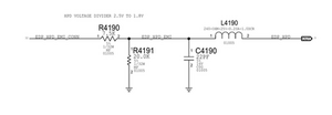
That pin connects to a resistor, a capacitor, another resistor, and an inductor. (R4190, C4190, R4191, and L4190). These 4 components all seemingly make up the EDP_HPD_EMI/EDP_HPD circuit. I measured the resistance of these components except for the capacitor which I just measured a diode mode reading on. I got the following measurements:
R4190: 7.48 kOhms
C4190: 0.483 (diode mode)
R4191: 20.04 kOhms
L4191: 1.2 Ohms
Unfortunately, I cannot know for sure what the proper values of these components are as I do not have another iPad 7 that works to check on. The two resistors in that circuit (R4190/R4191) reading quite different from another makes me suspicious. Then again, it may be totally normal. Without the schematic, it's hard for me to tell whether those two readings are supposed to be that way or if one of them (or both!) might be bad. I was hoping someone who might be a bit more familiar with this than me could look at what I have here and perhaps guide me on how to fix this problem or if I am even looking at the right place for the problem I am having in the first place.
I thought I'd mention that I did also check the EMI filters connected to J4100 and all of them seem to be fine.
I'm attaching a pic with my measurements on the components I have mentioned in this post. The added text in white is what I am measuring at each component. Thanks in advance.
EDIT: I just used the schematic from the iPad Air 2 and found the comparable circuit I am questioning (EDP_HPD_EMI_CONN). It looks like the 7.5 kOhm and 20 kOhm resistors are normal after all, so my earlier thoughts do not apply. So I guess I'm not sure what to do from here.

Esta é uma boa pergunta?