Ir para o conteúdo principal

Esta versão pode conter edições incorretas. Mude para o último instantâneo verificado.

O que você precisa

  1. , 屏幕: passo 1, imagem 1 %32
    Ferramenta utilizada nesse passo:
    iMac Intel 21.5" Cardboard Service Wedge
    $4.99
    Comprar
    • 一旦铰链可以自由移动,iMac 就会失去平衡,难以操作。维修可按图示完成,但使用 iMac 维修楔 更快、更容易。

    • 如果使用 iFixit纸板维修楔,请按照 这个指南 进行组装。

    • 在开始对 iMac 进行任何操作之前:拔下电脑电源插头,按住电源按钮十秒钟,使电源放电。

    • 请注意不要触摸电容器引线或电源背面任何暴露的焊点。只能用手触摸电路板的边缘。

  2. : passo 2, imagem 1 %32 : passo 2, imagem 2 %32
    • 从屏幕左侧电源按钮附近开始,将 iMac 打开工具插入玻璃面板和后机壳之间的缝隙。

    • iMac 开启工具上的轮毂可以防止你将轮子推入太深。如果使用其他工具,插入屏幕的深度不得超过 3/8"。否则,你很可能会切断天线排线并对电脑造成严重损坏。

    • 请轻轻撬!如果撬得太用力,玻璃可能会破裂。如果室温较低,可用吹风机加热边缘,以使粘合剂软化。

  3. : passo 3, imagem 1 %32 : passo 3, imagem 2 %32 : passo 3, imagem 3 %32
    • 该工具的使用方法就和使用披萨刀一样--沿着缝隙滚动工具,它就会从中间切开泡沫粘合剂。

    • 确保始终用切割轮后面的手柄推动。如果用力拉,切割轮可能会被拉出手柄。

    • 将工具沿屏幕左侧向上移动。

  4. : passo 4, imagem 1 %32 : passo 4, imagem 2 %32 : passo 4, imagem 3 %32
    • 继续沿着左上角向上移动工具。

  5. : passo 5, imagem 1 %32 : passo 5, imagem 2 %32
    • 沿屏幕左上方切开粘合剂。

  6. : passo 6, imagem 1 %32 : passo 6, imagem 2 %32
    • 沿着屏幕顶部继续操作。

    • 可能需要用工具来回切割几次,以确保尽可能多地分离粘合剂。

  7. : passo 7, imagem 1 %32 : passo 7, imagem 2 %32 : passo 7, imagem 3 %32
    • 将工具推到屏幕右上角周围。

  8. : passo 8, imagem 1 %32 : passo 8, imagem 2 %32
    • 沿屏幕右侧向下滚动工具。

  9. : passo 9, imagem 1 %32 : passo 9, imagem 2 %32
    • 将打开工具推至屏幕右侧底部。

    • 此时,请用工具绕着整个屏幕转一圈,以确保切开尽可能多的粘合剂。

  10. : passo 10, imagem 1 %32 : passo 10, imagem 2 %32 : passo 10, imagem 3 %32
    • 虽然打开工具可以切开大部分粘合剂,但屏幕仍会与外壳有轻微粘连。请使用塑料卡来切开最后的粘合剂。

    • 将 iMac 面朝上放在桌子上。

    • 从 iMac 的右上角开始,在显示屏和边框之间楔入一张塑料卡。

    • 请勿将塑料卡插入超过 3/8",否则可能会损坏内部组件。

  11. : passo 11, imagem 1 %32 : passo 11, imagem 2 %32
    • 将塑料卡轻轻向侧面扭转,在显示屏和边框之间形成间隙。

    • 慢慢移动,注意不要对显示屏玻璃造成太大压力,只需留出约 1/4 英寸的缝隙即可。

  12. : passo 12, imagem 1 %32 : passo 12, imagem 2 %32 : passo 12, imagem 3 %32
    • 将卡滑向显示屏中心,切开 iMac 右上角剩余的粘合剂。

    • 确保在 iSight 摄像头之前停止,否则可能会损坏它。

  13. : passo 13, imagem 1 %32 : passo 13, imagem 2 %32
    • 再次将塑料卡片楔入右上角,让它停留在那里,以防止粘合剂重新凝固。

  14. : passo 14, imagem 1 %32 : passo 14, imagem 2 %32 : passo 14, imagem 3 %32
    • 将第二张塑料卡插入 iMac 左上角显示屏与边框之间的缝隙。

  15. : passo 15, imagem 1 %32 : passo 15, imagem 2 %32
    • 轻轻向上扭转卡片,稍微增大显示屏和边框之间的空间。

    • 与另一侧一样,慢慢扭转,让粘合剂有时间分离,注意不要过度拉伸显示屏玻璃。

  16. : passo 16, imagem 1 %32 : passo 16, imagem 2 %32 : passo 16, imagem 3 %32
    • 将塑料卡向中间滑动,同样停在 iSight 摄像头之前。

  17. : passo 17, imagem 1 %32 : passo 17, imagem 2 %32
    • 将塑料卡片塞回左上角。

  18. : passo 18, imagem 1 %32 : passo 18, imagem 2 %32 : passo 18, imagem 3 %32
    • 如图所示,将两张塑料卡插入四角附近,轻轻向侧面扭转塑料卡,以增大显示屏与外壳之间的间隙。

    • 如果有粘在一起无法分开的部分,请停止扭动,用一张卡片剪掉剩余的粘胶。

    • 开始将显示屏顶部从边框上抬起。

    • 只需将显示屏抬起几英寸,显示屏的数据线和电源线仍连接在主板上。

  19. : passo 19, imagem 1 %32 : passo 19, imagem 2 %32
    • 用一只手托住显示屏,另一只手拔下显示屏电源线。确保将电缆从塑料片上拔出,而不是拉扯彩色电线。

    • 将显示屏向上抬起,以可以触碰到接口,但不要太用力,以免过度拉伸排线并对其连接造成压力(约 8 英寸)。

  20. : passo 20, imagem 1 %32 : passo 20, imagem 2 %32 : passo 20, imagem 3 %32
    • 用撬棒尖端翻起显示屏数据线上的金属固定支架。

    • 小心地将显示数据线从主板上的插座中拔出。

    • 确保将显示屏数据线接口从插座中直接拔出。

  21. : passo 21, imagem 1 %32 : passo 21, imagem 2 %32
    • 将显示屏抬起到接近垂直的位置。

    • 此时,沿着显示屏底部仍有一条粘合剂,它会像铰链一样将显示屏固定在框架上。你可以将显示屏上下移动几次来松开粘胶。

  22. : passo 22, imagem 1 %32 : passo 22, imagem 2 %32 : passo 22, imagem 3 %32
    • 请注意,不要触碰电容器引线或电源背面任何外露的焊点(红色方框)。

    • 抓住显示屏底部边缘粘胶条末端的小标签,将粘胶条拉向 iMac 顶部,将其取下。

    • 对另一条粘胶条重复这一步骤,然后取下。

    • 如果任一胶条在取下前断裂,可用塑料卡片划开剩余的胶条。

  23. : passo 23, imagem 1 %32 : passo 23, imagem 2 %32 : passo 23, imagem 3 %32
    • 将显示屏从框架上抬起,然后从 iMac 上取下。

    • 可能需要从一侧慢慢提起,与剩余的粘合剂剥离。

    • 要非常小心地操作显示屏--它很重,而且是玻璃制成的。

    • 在重新组装过程中,请查看我们的 显示屏粘合剂指南 以安装新粘合剂。

  24. Este passo não foi traduzido. Ajude a traduzi-lo

    : passo 24, imagem 1 %32 : passo 24, imagem 2 %32
    • Remove the following five Phillips screws holding the lower support bracket in place:

    • Four 3.2 mm screws

    • One 1.7 mm screw

    • On at least some EMC 2544 machines, all five screws are the same size.

    • You may need to peel up the display adhesive lining the bottom edge of the iMac enclosure to access the screws.

  25. Este passo não foi traduzido. Ajude a traduzi-lo

    : passo 25, imagem 1 %32
    • Remove the lower support bracket from the iMac enclosure.

  26. Este passo não foi traduzido. Ajude a traduzi-lo

    : passo 26, imagem 1 %32 : passo 26, imagem 2 %32
    • Use a spudger to loosen the right speaker cable's connector from its socket on the logic board.

    • It is useful to push downward on both short sides of the connector to "walk" it out of its socket. Be careful with the corners of the connectors, they can be easily broken off.

    • Pull the connector downwards to remove it from its socket.

  27. Este passo não foi traduzido. Ajude a traduzi-lo

    : passo 27, imagem 1 %32
    • Remove the two 10.0 mm T10 screws securing the right speaker to the rear enclosure.

  28. Este passo não foi traduzido. Ajude a traduzi-lo

    : passo 28, imagem 1 %32 : passo 28, imagem 2 %32
    • Pull the top of the right speaker away from the rear enclosure, about half an inch, to expose the antenna cable running down its right side.

  29. Este passo não foi traduzido. Ajude a traduzi-lo

    : passo 29, imagem 1 %32 : passo 29, imagem 2 %32 : passo 29, imagem 3 %32
    • Insert the tip of a spudger between the right speaker and the antenna cable that is routed into the speaker's right side.

    • Run the spudger down along the right side of the speaker to pry the antenna cable from its channel in the right speaker.

  30. Este passo não foi traduzido. Ajude a traduzi-lo

    : passo 30, imagem 1 %32 : passo 30, imagem 2 %32 : passo 30, imagem 3 %32
    • Pull the right speaker straight up about an inch, toward the top of the iMac.

    • Lift the right speaker straight up and remove it from the iMac. This may take some force, both hands and rocking the speaker right and left to get it out.

  31. Este passo não foi traduzido. Ajude a traduzi-lo

    : passo 31, imagem 1 %32
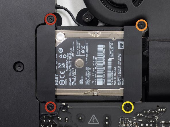
    • Remove the following screws securing the hard drive bracket to the rear enclosure:

    • Two 21 mm T10 Torx screws from the left-hand hard drive bracket.

    • One 9 mm T10 Torx screw.

    • One 27 mm T10 Torx screw.

  32. Este passo não foi traduzido. Ajude a traduzi-lo

    : passo 32, imagem 1 %32 : passo 32, imagem 2 %32
    • Remove the left and right hard drive brackets from the iMac.

  33. Este passo não foi traduzido. Ajude a traduzi-lo

    : passo 33, imagem 1 %32 : passo 33, imagem 2 %32 : passo 33, imagem 3 %32
    • The next few steps bring your hands close to the exposed face of the power supply. Do not touch the face of the power supply to avoid a high voltage shock from the many large capacitors attached to the board.

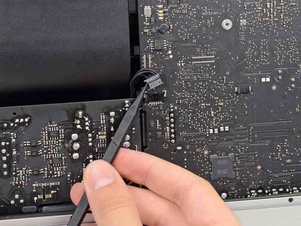
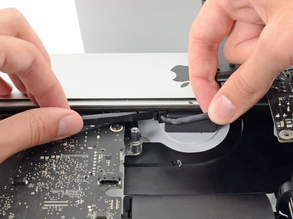
    • Use the tip of a spudger to push each side of the power button cable connector and gently "walk" it out of its socket.

  34. Este passo não foi traduzido. Ajude a traduzi-lo

    : passo 34, imagem 1 %32 : passo 34, imagem 2 %32
    • Gently push upward on each side of the power supply control cable connector with the tip of a spudger to gently "walk" it out of its socket.

  35. Este passo não foi traduzido. Ajude a traduzi-lo

    : passo 35, imagem 1 %32
    • Remove the two 7.2 mm T10 screws securing the power supply to the rear enclosure.

  36. Este passo não foi traduzido. Ajude a traduzi-lo

    : passo 36, imagem 1 %32 : passo 36, imagem 2 %32
    • When working on the power supply, be very careful not to touch the capacitor leads or any exposed solder joints on the back of the power supply. Only handle the board by the edges.

    • Tilt the power supply forward.

  37. Este passo não foi traduzido. Ajude a traduzi-lo

    : passo 37, imagem 1 %32 : passo 37, imagem 2 %32 : passo 37, imagem 3 %32
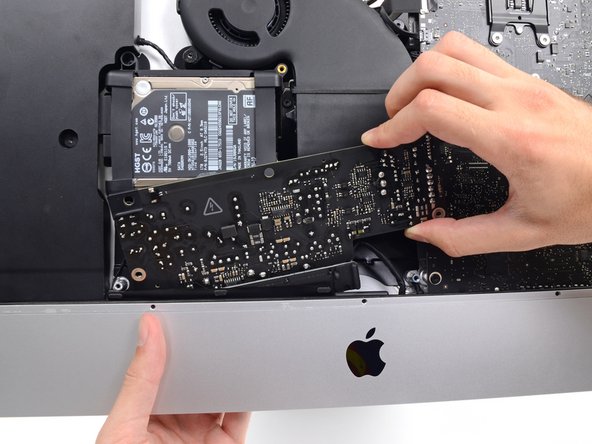
    • Pull the power supply slightly up and out from the rear enclosure.

    • Rotate the power supply counterclockwise, lifting the right side up about an inch higher than the left.

  38. Este passo não foi traduzido. Ajude a traduzi-lo

    : passo 38, imagem 1 %32 : passo 38, imagem 2 %32
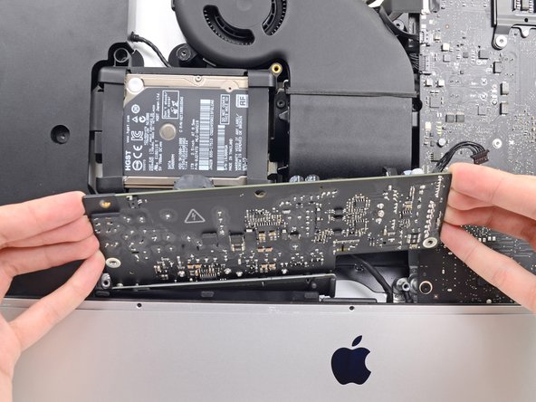
    • Slide the power supply to the right to clear the screw posts on the rear enclosure.

  39. Este passo não foi traduzido. Ajude a traduzi-lo

    : passo 39, imagem 1 %32 : passo 39, imagem 2 %32 : passo 39, imagem 3 %32
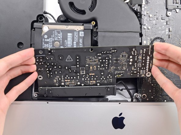
    • Rock the power supply forward and remove it from its recess in the rear enclosure.

    • Do not try to completely remove the power supply from the iMac yet—it is still connected to the logic board.

  40. Este passo não foi traduzido. Ajude a traduzi-lo

    : passo 40, imagem 1 %32 : passo 40, imagem 2 %32
    • Be very careful not to touch the capacitor leads or any exposed solder joints on the back of the power supply. Only handle the board by the edges.

    • Flip the top of the power supply towards you to access the DC power cable connection behind the logic board.

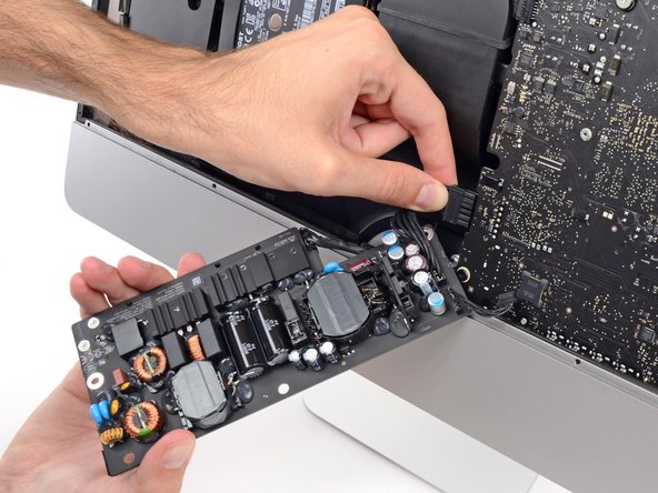
    • Squeeze the DC power cable connector tab and pull it straight out of its socket on the back of the logic board.

  41. Este passo não foi traduzido. Ajude a traduzi-lo

    : passo 41, imagem 1 %32 : passo 41, imagem 2 %32 : passo 41, imagem 3 %32
    • You may find it helpful to set the iMac down on its back on the table for the next couple of steps.

    • Use the flat end of a spudger to push the clip on the side of the AC inlet cable connector inward.

    • While holding on the release clip with the spudger, grasp the AC inlet cable, and pull the connector straight out of its socket.

  42. Este passo não foi traduzido. Ajude a traduzi-lo

    : passo 42, imagem 1 %32
    • Remove the power supply from the iMac.

  43. Este passo não foi traduzido. Ajude a traduzi-lo

    : passo 43, imagem 1 %32 : passo 43, imagem 2 %32
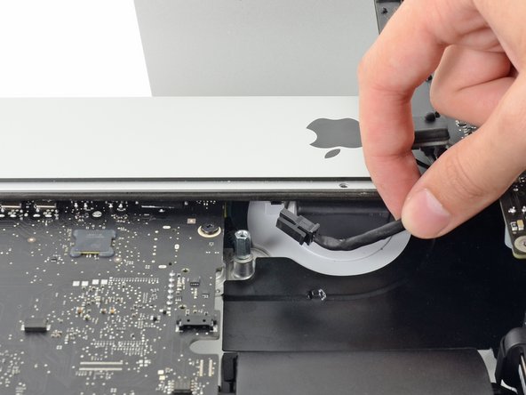
    • Gently pull the fan cable connector straight away from its socket on the logic board.

  44. Este passo não foi traduzido. Ajude a traduzi-lo

    : passo 44, imagem 1 %32
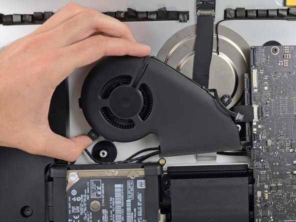
    • Remove the three 12.3 mm T10 shoulder screws securing the fan to the rear enclosure.

  45. Este passo não foi traduzido. Ajude a traduzi-lo

    : passo 45, imagem 1 %32 : passo 45, imagem 2 %32
    • Remove the fan from the iMac.

  46. Este passo não foi traduzido. Ajude a traduzi-lo

    : passo 46, imagem 1 %32 : passo 46, imagem 2 %32 : passo 46, imagem 3 %32
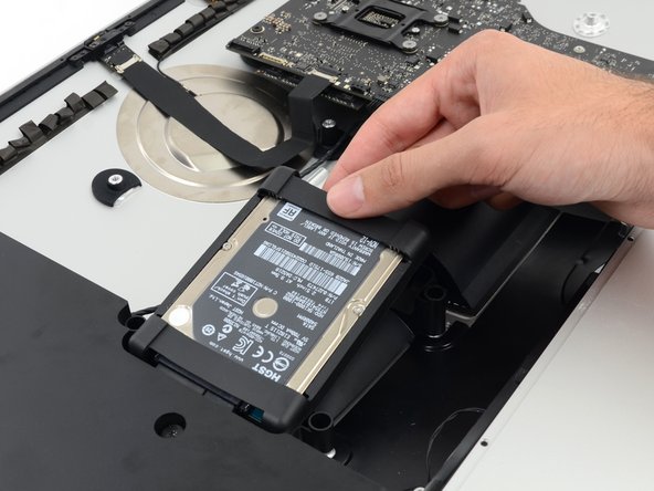
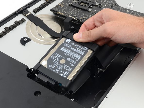
    • Lift the hard drive from the edge nearest the logic board and pull it slightly out of its recess.

    • The hard drive is attached by two cables, do not attempt to fully remove it from the iMac.

  47. Este passo não foi traduzido. Ajude a traduzi-lo

    : passo 47, imagem 1 %32 : passo 47, imagem 2 %32
    • Disconnect the SATA power cable.

  48. Este passo não foi traduzido. Ajude a traduzi-lo

    : passo 48, imagem 1 %32 : passo 48, imagem 2 %32
    • Unplug the SATA data cable from the hard drive.

  49. Este passo não foi traduzido. Ajude a traduzi-lo

    : passo 49, imagem 1 %32
    • Remove the hard drive from the iMac.

  50. Este passo não foi traduzido. Ajude a traduzi-lo

    : passo 50, imagem 1 %32
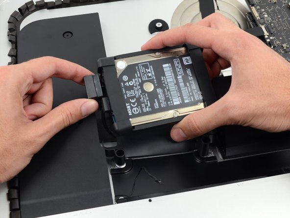
    • Remove the single 7.2 mm T10 screw securing the hard drive tray to the rear enclosure.

  51. Este passo não foi traduzido. Ajude a traduzi-lo

    : passo 51, imagem 1 %32
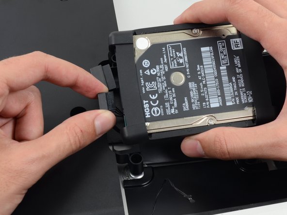
    • Remove the hard drive tray from the rear enclosure.

  52. Este passo não foi traduzido. Ajude a traduzi-lo

    : passo 52, imagem 1 %32 : passo 52, imagem 2 %32
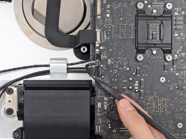
    • Push on each side of the left speaker cable connector with the tip of a spudger and gently "walk" it out of its socket.

  53. Este passo não foi traduzido. Ajude a traduzi-lo

    : passo 53, imagem 1 %32 : passo 53, imagem 2 %32
    • De-route the left speaker cable by pulling it straight up out of the retaining clip in the back of the rear enclosure.

  54. Este passo não foi traduzido. Ajude a traduzi-lo

    : passo 54, imagem 1 %32 : passo 54, imagem 2 %32 : passo 54, imagem 3 %32
    • In a similar fashion as the previous step, de-route the SATA data and power cables up out of the retaining clip.

  55. Este passo não foi traduzido. Ajude a traduzi-lo

    : passo 55, imagem 1 %32 : passo 55, imagem 2 %32 : passo 55, imagem 3 %32
    • Use the flat edge of a spudger to flip up the metal retaining bracket on the iSight camera cable connector.

    • Pull the iSight camera cable straight out of its socket on the logic board.

    • This is a delicate connector that can be easily damaged.

  56. Este passo não foi traduzido. Ajude a traduzi-lo

    : passo 56, imagem 1 %32 : passo 56, imagem 2 %32 : passo 56, imagem 3 %32
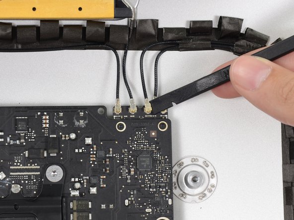
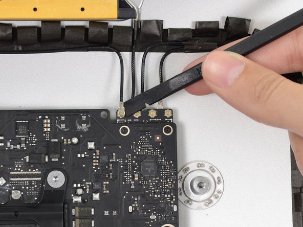
    • Use the flat edge of a spudger to disconnect each of the four antenna connectors from the AirPort/Bluetooth card.

    • Note the original positions for each connector when reconnecting the cables.

  57. Este passo não foi traduzido. Ajude a traduzi-lo

    : passo 57, imagem 1 %32
    • If brackets secure the four antenna cables, remove the two T5 Torx screws from the brackets.

  58. Este passo não foi traduzido. Ajude a traduzi-lo

    : passo 58, imagem 1 %32 : passo 58, imagem 2 %32 : passo 58, imagem 3 %32
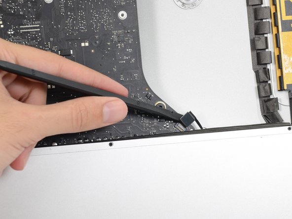
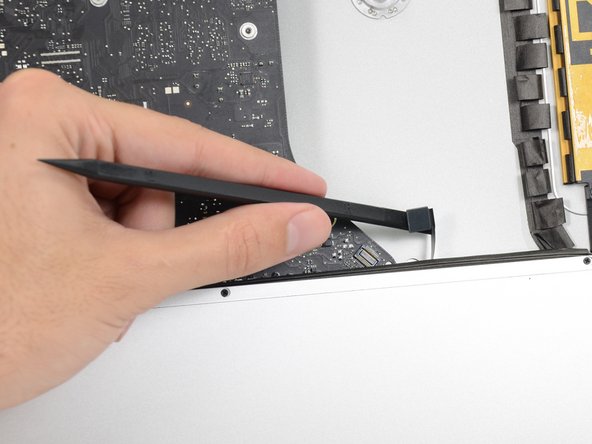
    • Use the flat edge of a spudger to pry the headphone jack cable connector from its socket on the logic board.

    • Push the cable slightly to the right.

  59. Este passo não foi traduzido. Ajude a traduzi-lo

    : passo 59, imagem 1 %32
    • Remove the following screws securing the exhaust duct to the rear enclosure:

    • Two 6.3 mm T8 screws

    • Two 4.7 mm T8 screws

  60. Este passo não foi traduzido. Ajude a traduzi-lo

    : passo 60, imagem 1 %32
    • Remove the four 7.2 mm T10 screws securing the logic board to the rear enclosure.

    • Depending on the age and model of your iMac, a T9 driver may work best.

  61. Este passo não foi traduzido. Ajude a traduzi-lo

    : passo 61, imagem 1 %32 : passo 61, imagem 2 %32 : passo 61, imagem 3 %32
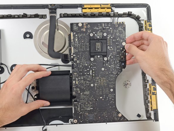
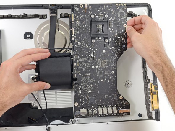
    • Tilt the top of the logic board away from the rear enclosure.

    • Lift the logic board straight up and out of the iMac.

    • Be careful not to snag the board on any of the rear case's screw posts.

    • The I/O boards at the bottom of the logic board will be the greatest challenge. It is recommended to pull gently to avoid any damage.

    • During reassembly of the logic board, pay attention to the position of the I/O connectors. When the board is back in the case, insert a USB or Thunderbolt cable into one of the connectors to align it perfectly.

  62. Este passo não foi traduzido. Ajude a traduzi-lo

    : passo 62, imagem 1 %32 : passo 62, imagem 2 %32 : passo 62, imagem 3 %32
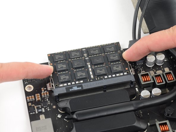
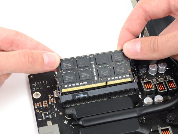
    • Release the tabs on each side of the RAM module by simultaneously pushing each tab away.

    • The RAM module should pop up slightly from its socket.

    • Grab the top left and right corners of the RAM module and carefully pull it straight out of its socket.

    • Repeat the process to remove additional RAM modules as necessary.

  63. Este passo não foi traduzido. Ajude a traduzi-lo

    : passo 63, imagem 1 %32 : passo 63, imagem 2 %32 : passo 63, imagem 3 %32
    • Disconnect and remove the SATA data and power cables from the logic board.

  64. Este passo não foi traduzido. Ajude a traduzi-lo

    : passo 64, imagem 1 %32
    • Remove the four 12 mm T10 shoulder screws from the spring plate behind the CPU.

  65. Este passo não foi traduzido. Ajude a traduzi-lo

    : passo 65, imagem 1 %32
    • Remove the spring plate from behind the CPU heat sink.

  66. Este passo não foi traduzido. Ajude a traduzi-lo

    : passo 66, imagem 1 %32
    • Lift and remove the backing plate from behind the CPU heat sink.

    • The backing plate has two posts that fit into alignment holes in the logic board and heat sink.

  67. Este passo não foi traduzido. Ajude a traduzi-lo

    : passo 67, imagem 1 %32 : passo 67, imagem 2 %32
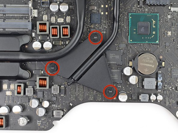
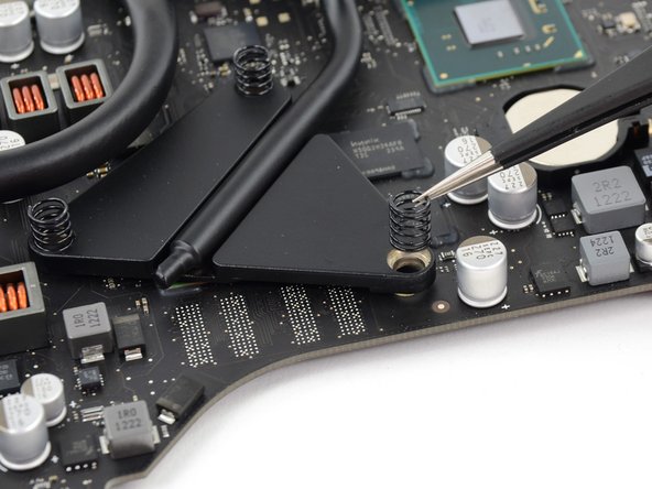
    • Remove the three 12 mm T8 Torx screws securing the GPU heat sink to the logic board.

    • Remove the three springs left behind.

    • These springs might come up with the screws; be careful not to lose track of them.

  68. Este passo não foi traduzido. Ajude a traduzi-lo

    : passo 68, imagem 1 %32 : passo 68, imagem 2 %32
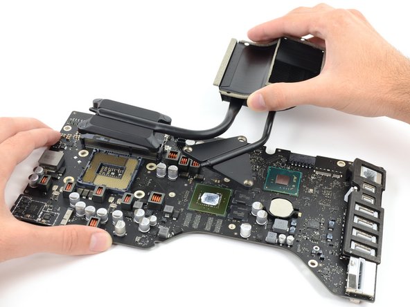
    • Lift and remove the heat sink up off the logic board.

    • The CPU will most likely detach with the heat sink, so be careful about where you lay it down.

  69. Este passo não foi traduzido. Ajude a traduzi-lo

    : passo 69, imagem 1 %32 : passo 69, imagem 2 %32
    • The CPU will most likely be stuck to the heat sink with thermal compound.

    • Insert the flat edge of a spudger between the CPU and heat sink.

    • Gently pry the CPU off the heat sink by slightly twisting the spudger upwards.

  70. Este passo não foi traduzido. Ajude a traduzi-lo

    : passo 70, imagem 1 %32
    • Remove the CPU from the heat sink. Be careful not to touch the contacts.

  71. Este passo não foi traduzido. Ajude a traduzi-lo

    : passo 71, imagem 1 %32
    • Heat sink remains.

    • To reinstall the heat sink, see our thermal paste guide for instructions on cleaning and preparing the thermal surfaces and applying a new layer of thermal compound onto the CPU and GPU dies.

Linha de Chegada

5 outras pessoas executaram este guia.

Sam Goldheart

Membro desde: 10/18/12

466.117 Reputação

Autoria de 538 guias

Equipe

iFixit Membro de iFixit

Staff

Membros da 136

Autoria de 17.400 guias

0 comentários

Adicione um comentário

Exibir estatísticas:

Últimas 24 horas: 1

Últimos 7 dias: 8

Últimos 30 dias: 37

Duração total: 3,940