Introdução
Tripped over your power cord? At least you don't have to replace the entire logic board.
O que você precisa
-
-
Use a coin to rotate the battery locking screw 90 degrees clockwise.
-
Lift the battery out of the computer.
-
-
-
Pull the keyboard release tabs toward you and lift up on the keyboard until it pops free.
-
If the keyboard does not come free, use a small flathead screwdriver to turn the keyboard locking screw 180 degrees in either direction and try again.
-
Flip the keyboard over, away from the screen, and rest it face-down on the trackpad area.
-
-
-
Pull the keyboard cable up from the logic board, holding the cable as close to the connector as possible.
I feel this step needs clarification: Are just lifting the cable away from the shield, or are we removing the cable entirely?
-
-
-
Your laptop should look approximately like this.
Remove the two long screws along the back edge, and the shorter screw in the middle. Torx T-8. Pry up the rubber feet, and unscrew the three Phillips screws that hold the feet in place. Putting the silver collars back requires a little bit of fiddling to get them oriented correctly so they sit flush with the bottom case.
-
-
-
Remove the three 5.2 mm newly-revealed Phillips screws.
this should be after step 12 no?
This should be step 3.
-
-
-
Remove the one 10 mm and two 20 mm hex screws using a 2mm hex. Alternatively, a T8 Torx screwdriver key will do.
FYI, the two screws at the top of this picture are longer than the one in the middle of the case. Don't mix them up!
Two of the hex screws here got stripped. Please, replace them ASAP and I would recommend not putting them back just to not risk making them stuck. I spent 30 minutes trying to get those two out.
-
-
-
There is a slot on the wall of the battery compartment that locks the lower case in place. Use a small flathead screwdriver to pry out the slot's lower rim and pull up on the lower case to free the slot from the tabs holding it.
If your iBook's been opened many times (Like mine has been) then this piece may be broken.
If it's cracked down the middle or a little off, what you'll want to do is use your bent paperclip from a few steps later (or another screwdriver) and pull the second piece away from the shell when you start lifting. should pull right out
-
-
-
-
Continue to run the spudger around the front, right corner. There are two tabs on the port side of the computer, one near the front corner and one near the sound out port.
isn’t this step out of order? It belongs much later I think
This should be step 4.
-
-
-
Once the front and sides of the lower case are free, turn the computer so that the back is facing you and pull the lower case up and toward you until the back tabs pop free (it may be helpful to jiggle the case up and down).
Be aware that you may need to use a spudger at the front of the computer to separate the metal shield from the bottom case.
-
-
-
Remove the small greasy springs with white plastic caps from either side of the battery contacts.
Clean the springs and put them back, hopefully without breaking the small plastic pieces on the top of each spring. One of mine broke off and the other one was already missing. Poor design.
-
-
-
Remove the five 5.8 mm Phillips screws from the bottom shield.
-
Peel back the yellow tape and foil shielding outlined in the image.
-
-
-
Remove the following 4 screws on the bottom of the computer:
-
Two 3 mm Phillips from the left side of the computer.
-
One 4.5 mm Phillips near the latch mechanism (this screw may be missing in 800 MHz iBooks)
-
One 14.2 mm Phillips near the front, right corner.
This photo is a little confusing. The shield should be off, which would show the correct positions of the yellow and orange screws. (The orange circle is in the wrong place.) Furthermore, these screws don't need to be removed at this stage (they hold the logic board to the frame). And finally, on my 800 MHz machine, BOTH these screws are 6 mm in length.
Citação de commenter:
This photo is a little confusing. The shield should be off, which would show the correct positions of the yellow and orange screws. (The orange circle is in the wrong place.) Furthermore, these screws don't need to be removed at this stage (they hold the logic board to the frame). And finally, on my 800 MHz machine, BOTH these screws are 6 mm in length.
The two red screws and the orange screw have to be removed (iBook G3 600 MHz).
On my 800, the yellow screw is a 6mm Phillips with a wide head.
-
-
-
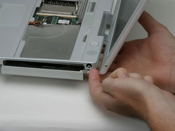
Use a straightened paperclip to open the optical drive tray.
-
-
-
Pull the optical drive out just enough so that you can access and remove a Phillips screw near the battery compartment.
i think that we can leave that one out on re-assembly
If you fully extend the tray it's fairly easy to get to the screw by going inside the rails. And grab it with tweezers.
When re-installing use something sticky on your screwdriver to hold the screw in place, or it's never going in. The sleep magnet is nasty at grabbing your screw and pulling it away. (Doesn't hurt to have something sticky on it for taking it out too...)
If you're doing this type of work, what's wonderful is to have a set of technicians magnetic drivers. I have a set of twelve that are about 6"long, and very skinny. Phillips 1, 0, 00, & 000 . . . Torx 6, 7, 8, 9, & 10 . . . and slotted 5/64", 3/32", & 1/8". I wish I could remember where I got them, but you could probably Google it. One of the smaller magnetic Phillips was perfect for removal AND replacing this screw. A word of CAUTION, though . . . probably best to keep any magnetic tools away from sensitive components on the PC board.
To anyone that’s absolutely stuck: there is a little slot along the drive where the screwdriver fits in. I didn’t know this for at least 3 times I took apart this computer, and finding this now has helped me sooooo much.
-
-
-
Pull the optical drive a bit more so that you can access and remove a second Phillips screw near the power receptacle.
-
-
Ferramenta utilizada neste passo:Tweezers$4.99
-
Turn over the computer and open it.
-
Use tweezers (or a refrigerator magnet) to remove the magnet covering a Phillips screw near the middle of the computer.
-
-
-
Lift the upper case from the left side and use your other hand to pull out the right side in order to clear the power receptacle.
I had one (800MHz), that on the B&W power cable, it was so tight that it pulled the socket from the PC board. Never had that happen before, although the potential exists on many of them. Needless to say, that machine is now allocated as a parts unit. What I found is the safest way, and really not all that much trouble, is the remove the 5 screws, peel back the tape, and remove the speaker/switch units from the top cover. Worked for me, and avoided the risk mentioned above.
-
-
-
Lift the upper case enough to disconnect the blue and white power cable from the logic board. Using your fingernails or a dental pick, carefully pry the connector from its socket. Make sure you're pulling only on the connector and not on the socket.
Not unless you have to! Most parts can be removed with this left in. Don't try pulling on it unless you have to, it can easily break the logic board. Just tilt the upper case up to lean it on the display.
Much easier if you do this after Step 37.
It is alot easier to get at after you pull the speaker cable out. Use something small to pop it out of place though, I broke my extra spare being a little too hasty.
This connector has a small catch on the right. slipping a sharp object (eg: pin) between the connector and it holder will release the catch. The connector should now come off easily.
I put this comment in the last step, but perhaps it should go here as well:
I had one (800MHz), that on the B&W power cable, it was so tight that it pulled the socket from the PC board. Never had that happen before, although the potential exists on many of them. Needless to say, that machine is now allocated as a parts unit. What I found is the safest way, and really not all that much trouble, is the remove the 5 screws, peel back the tape, and remove the speaker/switch units from the top cover. Worked for me, and avoided the risk mentioned above.
This is where my journey ended as well. The blue and white power cable socket lifted straight off the logic board, even though I was being super careful. Can't win em all! But I'd suggest if there's any way of doing this, without unplugging this, then do that.
-
-
-
Lift the upper case off completely and disconnect the red and black speaker cable from the logic board. As before, make sure you're pulling only on the connector and not on the socket.
There is a magnet covering a screw to the left of the serial number located in the upper center of the upper case. Remove the magnet, smooth,round and small, and loosen (doesn't need to come out) the screw to remove the upper case. Proceed to disconnecting the speaker and power cables. NOTE: this magnet is not the same one indicated in step image 33.
Oops - second attempt to install a hard drive in this; the second time unlucky. Last time I left the red and black cable in place; this time, I ripped the socket mentioned out.
-
-
-
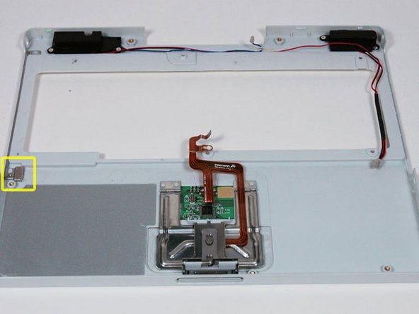
Your laptop should look approximately like this.
I found that at this point I was able to avoid any further steps by removing the screw from the DC in board and the flip the machine over to reveal its connection to the board. I removed this connection and then was able to wiggle the board out and snake the cord out. Avoiding Step 38 saves a lot of screw removal. Not to mention not having to remove the CD Drive also saves a lot of time.
Just be careful when doing this that you do not force the board out of its place. There is room to remove it, but it is a gentle task.
-
-
-
Remove the following 14 screws (some models may be missing a couple of screws):
-
One 2.5 mm Phillips.
-
Six 3.5 mm Phillips.
-
One 4.5 mm Phillips near the sleep light with a small shaft.
-
Two 4.5 mm Phillips with larger shafts.
-
Four 5 mm Phillips
-
If a screw is inserted in the left hole, the 14.2 mm screw in step 24 can not be inserted to hold the top case down.
Citação de neato:
If your iBook is like mine (700MHz) The yellow screw was attached from the bottom through the bottom case and had to be removed earlier in order to remove the bottom case. Also the the green screw pictured to the left was missing already removed.
It's the same to iBook G3 600 MHz
-
-
-
Peel back three strips of yellow tape in the bottom left corner.
-
Peel back one strip of foil tape in the upper left corner and another near where the trackpad connects to the logic board.
There is also foil tape, cetre front, in the cutout for the catch mechanism
-
-
-
On the bottom of the computer, disconnect the DC-In cable from the logic board.
No reason to disconnect the DC-In cable. Nothing we are doing requires it disconnected and it is a fragile and vital piece of a "working machine."
-
-
-
Peel back the orange ribbon cable to reveal a single Phillips screw. Remove this screw to free the optical drive from the metal framework.
-
-
-
Remove the single 5.5 mm Phillips screw securing the DC-In board to the metal framework.
-


To reassemble your device, follow these instructions in reverse order.
To reassemble your device, follow these instructions in reverse order.
Cancelar: não concluí este guia.
18 outras pessoas executaram este guia.
Documentos anexados

Um comentário
What was the symptom(s) leading to the diagnosis that this board was in need of being replaced??
Also unplug the computer just before taking the two steps described above.
Ken Horner - Responder