Esta versão pode conter edições incorretas. Mude para o último instantâneo verificado.
O que você precisa
-
Este passo não foi traduzido. Ajude a traduzi-lo
-
It should be noted that these guides are written based on a late-model eMac (2005, 1.42GHz, DDR). They will differ slightly from the older model eMacs that use PC-133 RAM.
-
Lay the eMac screen-down on a flat surface. I've found it convenient to use a carpeted floor because the computer is so heavy.
-
Remove the single phillips #2 screw on the RAM door, and remove the door
-
The screw is captive in the door, so don't worry about losing it.
-
-
Este passo não foi traduzido. Ajude a traduzi-lo
-
You can read more about CRT safety procedures here. If you aren't experienced with working on devices featuring a CRT, it's recommended that you don't proceed any further.
-
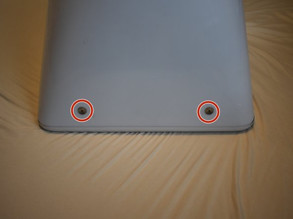
On the bottom side of the eMac, remove the following screws:
-
A single 2.5mm hex screw
-
Two #2 phillips screws
-
-
Este passo não foi traduzido. Ajude a traduzi-lo
-
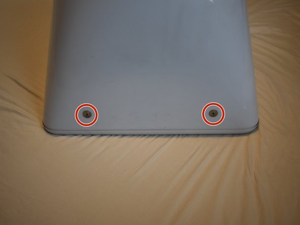
Remove two 2.5mm hex screws from each of the other sides of the computer.
-
-
Este passo não foi traduzido. Ajude a traduzi-lo
-
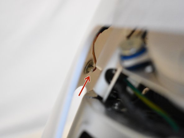
Now, the shell can almost be separated from the computer.
-
Lift the housing enough to allow you to fit your hand through the access door, and disconnect the cable at the power button.
-
-
Este passo não foi traduzido. Ajude a traduzi-lo
-
Now the entire shell can be removed from the computer.
-
-
Este passo não foi traduzido. Ajude a traduzi-lo
-
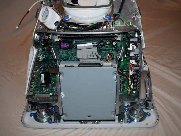
The motherboard access panel is held on by 4 phillips #2 screws.
-
Remove the screws, then use your fingers to pull on the top tabs to separate the panel from the computer frame.
-
-
-
Este passo não foi traduzido. Ajude a traduzi-lo
-
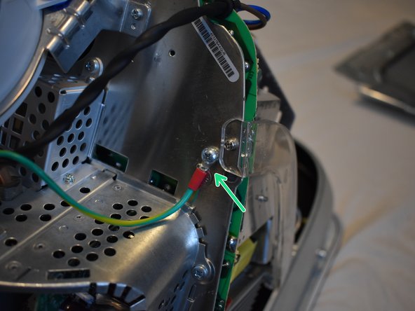
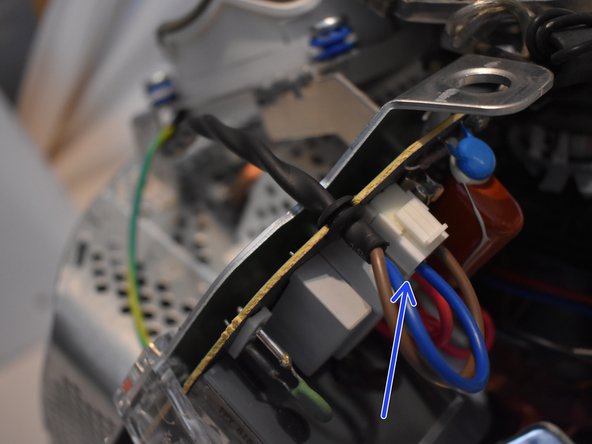
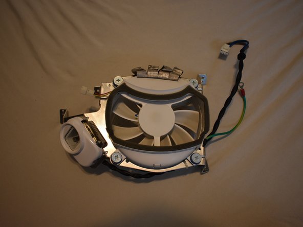
To remove the fan assembly, several cables must be disconnected first:
-
3-pin fan cable
-
Ground wire, requires phillips #2 screwdriver
-
2-pin AC cable to power supply
-
-
Este passo não foi traduzido. Ajude a traduzi-lo
-
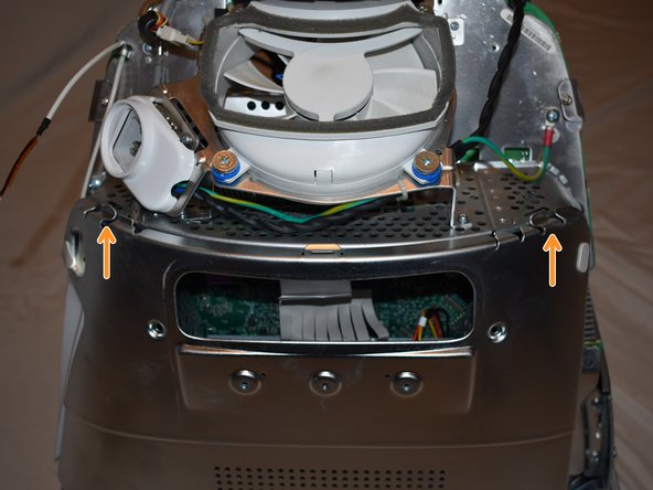
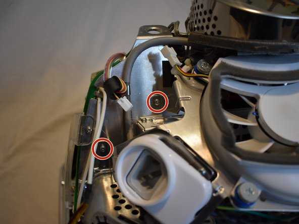
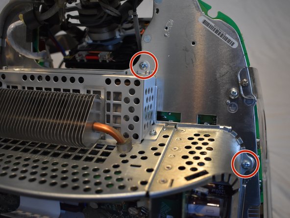
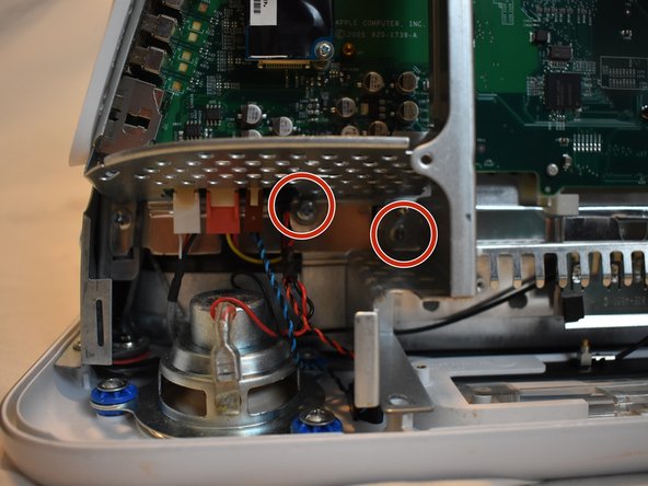
Now remove the following screws securing the fan assembly:
-
3x coarse thread phillips #2
-
1x machine thread phillips #2
-
-
Este passo não foi traduzido. Ajude a traduzi-lo
-
There may be a zip tie holding another cable to the fan assembly, cut it to remove the fan assembly.
-
-
Este passo não foi traduzido. Ajude a traduzi-lo
-
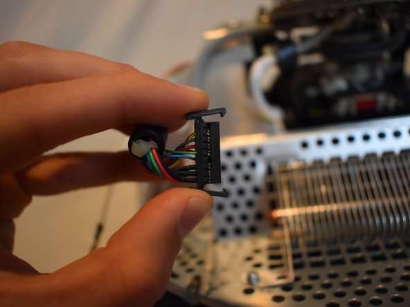
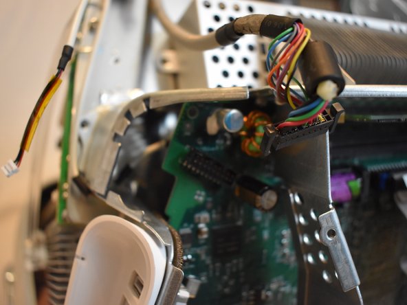
There are four connectors at the bottom of the motherboard that must be removed.
-
-
Este passo não foi traduzido. Ajude a traduzi-lo
-
There is a large display connector that must be removed. This can be done by squeezing the tabs and pulling.
-
-
Este passo não foi traduzido. Ajude a traduzi-lo
-
The power button cable may be tucked in the casing, you will need to un-tuck it.
-
-
Este passo não foi traduzido. Ajude a traduzi-lo
-
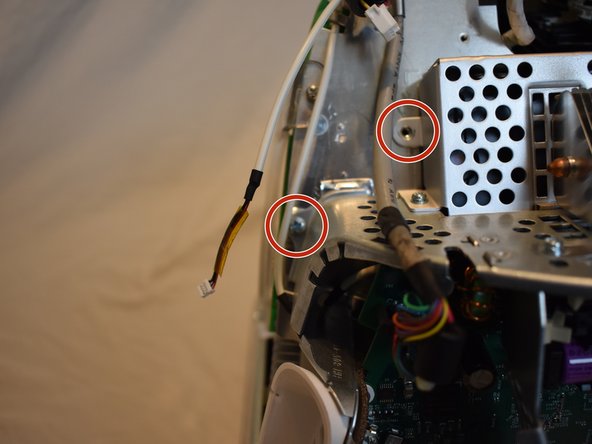
There are several phillips #2 screws that hold the eMac motherboard assembly to the rest of the computer. They will all need to be removed.
-
2 large ones near the drive bay door.
-
7 smaller ones scattered around
-


Cancelar: não concluí este guia.
5 outras pessoas executaram este guia.

Equipe
