Esta versão pode conter edições incorretas. Mude para o último instantâneo verificado.
O que você precisa
-
Este passo não foi traduzido. Ajude a traduzi-lo
-
Use a pair of tweezers to remove the sticker hiding the first screw on the back panel, near the base.
-
-
Este passo não foi traduzido. Ajude a traduzi-lo
-
Use a pair of blunt tweezers to peel back the large sticker on the back panel to reveal the second screw.
-
-
Este passo não foi traduzido. Ajude a traduzi-lo
-
Use a T8 Torx driver to remove the two 7.4 mm-long screws securing the back panel.
-
-
Este passo não foi traduzido. Ajude a traduzi-lo
-
Insert the flat end of a spudger into the gap between the back panel and the shell, near the left side of the base.
-
Pry up the back panel to release it from the locking clips.
-
-
Este passo não foi traduzido. Ajude a traduzi-lo
-
Insert the flat end of a spudger into the gap between the back panel and the shell, near the right side of the base.
-
Pry up the back panel to release it from the locking clips.
-
-
Este passo não foi traduzido. Ajude a traduzi-lo
-
Grip the back panel at the opening you just created and pull it up and away from the shell to unclip the long edges.
-
-
Este passo não foi traduzido. Ajude a traduzi-lo
-
Tilt the back panel up and pull it away from the top edge of the shell to release it from the gap.
-
Remove the back panel.
-
-
Este passo não foi traduzido. Ajude a traduzi-lo
-
Use a T8 Torx driver to remove the three screws securing the fan to the center chassis:
-
One 10.5 mm pancake screw
-
Two 8.8 mm screws
-
-
Este passo não foi traduzido. Ajude a traduzi-lo
-
Use your fingers or a pair of blunt tweezers to grip the edges of the fan cable connector, and pull up to disconnect it from the center chassis.
-
-
Este passo não foi traduzido. Ajude a traduzi-lo
-
Use the flat end of a spudger to lift up on the locking tab holding the base to the shell.
-
-
Este passo não foi traduzido. Ajude a traduzi-lo
-
Grip the base and rotate it counterclockwise to unlock it from the shell.
-
Remove the base.
-
-
Este passo não foi traduzido. Ajude a traduzi-lo
-
Use a T8 Torx driver to remove the two 8.8 mm screws securing the optical drive's vibration isolator to the shell: one on the base and one on the top of the isolator.
-
-
Este passo não foi traduzido. Ajude a traduzi-lo
-
Lift up the optical drive's vibration isolator to remove it.
-
-
Este passo não foi traduzido. Ajude a traduzi-lo
-
Use a pair of blunt tweezers to grip the edges of the optical drive power connector and pull up to disconnect it from the optical drive.
-
Use your fingers to pull up and disconnect the data cable from the optical drive.
-
-
Este passo não foi traduzido. Ajude a traduzi-lo
-
Grip the top edge of the optical drive and pull it out of its slot in the shell to remove it.
-
-
-
Este passo não foi traduzido. Ajude a traduzi-lo
-
Use the flat end of a spudger to flip open the metal locking tab on the USB port ribbon cable.
-
-
Este passo não foi traduzido. Ajude a traduzi-lo
-
Use a pair of tweezers to pull up on the black plastic pull tab to disconnect the USB port cable.
-
-
Este passo não foi traduzido. Ajude a traduzi-lo
-
Use the pointed end of a spudger to depress the metal tab on the side of the power button cable's board connector.
-
With the metal tab depressed, use a pair of tweezers to pull up on the pull tab to disconnect the power button cable from the center chassis.
-
-
Este passo não foi traduzido. Ajude a traduzi-lo
-
Use a T8 Torx driver to remove the three 7.4 mm screws securing the center chassis assembly to the shell.
-
-
Este passo não foi traduzido. Ajude a traduzi-lo
-
Gently peel the taped USB port ribbon cable off of the heatsink.
-
-
Este passo não foi traduzido. Ajude a traduzi-lo
-
Grip the center chassis and pull it towards the green fan grille at the top of the shell, uncoupling the guide pegs from the shell.
-
Lift out the center chassis assembly to remove it from the shell.
-
-
Este passo não foi traduzido. Ajude a traduzi-lo
-
Unlatch the chassis strap from the right side of the power supply.
-
-
Este passo não foi traduzido. Ajude a traduzi-lo
-
Pull the chassis strap over and off of the power supply.
-
Once the strap is off of the power supply, set the loose section to the side.
-
-
Este passo não foi traduzido. Ajude a traduzi-lo
-
Use a T8 Torx driver to remove the three screws securing the power cable port to the chassis:
-
Two 13.1 mm screws
-
One 35 mm screw
-
-
Este passo não foi traduzido. Ajude a traduzi-lo
-
Lift the power connector out of its recess in the chassis.
-
-
Este passo não foi traduzido. Ajude a traduzi-lo
-
Unlatch and open the lid on the power cable's plastic guide.
-
-
Este passo não foi traduzido. Ajude a traduzi-lo
-
Lift the power cable out from underneath the extra section of the cable guide.
-
-
Este passo não foi traduzido. Ajude a traduzi-lo
-
Use a T8 Torx driver to remove the 8.8 mm screw securing the power supply corner cover.
-
-
Este passo não foi traduzido. Ajude a traduzi-lo
-
Use your fingers or a pair of tweezers to lift and remove the power supply corner cover.
-
-
Este passo não foi traduzido. Ajude a traduzi-lo
-
Use a T8 Torx driver to remove the three 9.6 mm screws securing the accessory antenna board to the center chassis.
-
-
Este passo não foi traduzido. Ajude a traduzi-lo
-
Grip the antenna board and pull it directly away from the center chassis to disconnect it.
-
-
Este passo não foi traduzido. Ajude a traduzi-lo
-
Use a T8 Torx driver to remove the nine screws securing the board shield:
-
Six 8.8 mm black screws
-
Two 35 mm silver screws
-
One 13.1 mm silver screw
-
-
Este passo não foi traduzido. Ajude a traduzi-lo
-
Lift up the board shield to remove it from the center chassis.
-
-
Este passo não foi traduzido. Ajude a traduzi-lo
-
Disconnect the chassis strap from the locking tabs on either side of the power supply.
-
-
Este passo não foi traduzido. Ajude a traduzi-lo
-
Grip and compress the locking tab on the 10-pin power connector.
-
While compressing the locking tab, lift the connector straight up to disconnect it from the board.
-
-
Este passo não foi traduzido. Ajude a traduzi-lo
-
Grip and compress the locking tab on the 2-pin power connector.
-
While compressing the locking tab, lift the connector straight up to disconnect it from the board.
-
-
Este passo não foi traduzido. Ajude a traduzi-lo
-
Open the lid on the power supply's plastic cable guide.
-
-
Este passo não foi traduzido. Ajude a traduzi-lo
-
Use a T8 Torx driver to remove the four screws securing the power supply around its perimeter:
-
Three 35 mm silver screws
-
One 8.8 mm black screw
-
-
Este passo não foi traduzido. Ajude a traduzi-lo
-
Use a T8 Torx driver to remove the three 8.8 mm screws securing the Wi-Fi antenna board.
-
-
Este passo não foi traduzido. Ajude a traduzi-lo
-
Grip the antenna board and pull it directly away from the center chassis to disconnect it.
-
Remove the antenna board.
-
-
Este passo não foi traduzido. Ajude a traduzi-lo
-
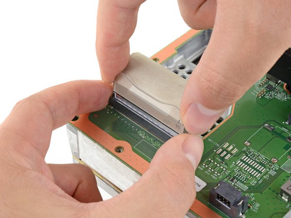
Grip the base of the interconnect cable connector with your fingers.
-
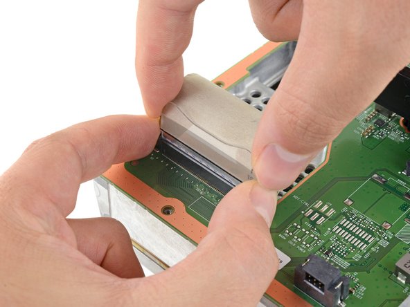
Depress each side of the connector to unlock the cable locking tabs.
-
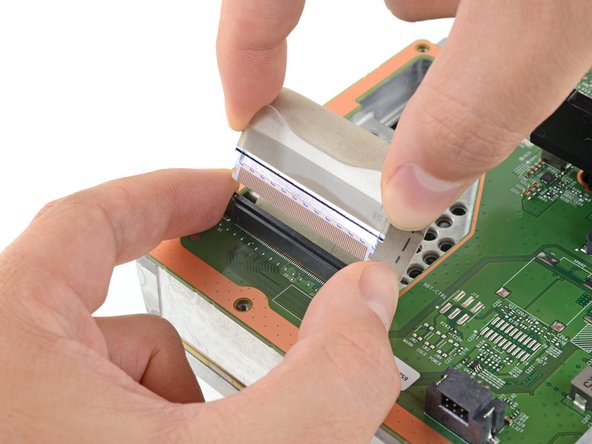
With the locking tabs depressed, grip the edges of the interconnect cable and pull it straight out of the connector to disconnect it.
-
-
Este passo não foi traduzido. Ajude a traduzi-lo
-
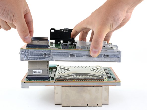
Lift the center chassis off of the motherboard and heatsink assembly.
-
Route the interconnect cable through the cutout on the center chassis as you remove it.
-
-
Este passo não foi traduzido. Ajude a traduzi-lo
-
Use the flat end of a spudger to pry up the edges of the metal SSD shield.
-
Remove the SSD shield.
-
-
Este passo não foi traduzido. Ajude a traduzi-lo
-
Use a T8 Torx driver to remove the 5.2 mm screw securing the SSD.
-
-
Este passo não foi traduzido. Ajude a traduzi-lo
-
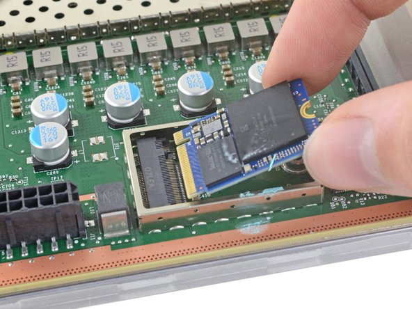
Grip the end of the SSD and pull it away from its M.2 board connector to remove it.
-


Cancelar: não concluí este guia.
16 outras pessoas executaram este guia.


10 comentários
What name cards are compatible to install in the series x and what is the max storage capacity that can be installed?
Theoretically speaking, any M.2 NVMe 2230 SSD PCIe 4.0 that’s been formatted to New Technology File System (NTFS, proprietary MS formatting for Windows 7 onwards) should work. You’ll also need to make a Xbox OS installer USB as well, in the same style as making a Media Creation Tool for Windows 8.1 and 10 installation on new HDDs and SSDs.
https://support.xbox.com/en-AU/help/hard...
The issue I want to find out is which sector allocation value is required -> leads into the theoretical max storage of a single internal SSD (around 16TB assuming a 4KB sector size). https://docs.microsoft.com/en-us/windows...
The Xbox SSDs are all PCIe 4.0x2 so you need WD CH (NOT PC) SN530/SN560 or SSSDTC/Lite-On XA1 SSDs.
The CH SN560 is a newer model that has faster read speeds (2400 vs 2000 MB/s) but is much more rare. Most of the CH WD SSDs on the market is CH SN530.
Mike -
Correct the SSD has a hidden partition that contains encrypted info marrying the SSD to the main board. However you can do a bit by bit clone of this partition providing your drive hasn't failed already.
Dunno about size or make I suspect you can only install 1GB until MS update the firmware and release models with bigger SSDs in.