Esta versão pode conter edições incorretas. Mude para o último instantâneo verificado.
O que você precisa
-
Este passo não foi traduzido. Ajude a traduzi-lo
-
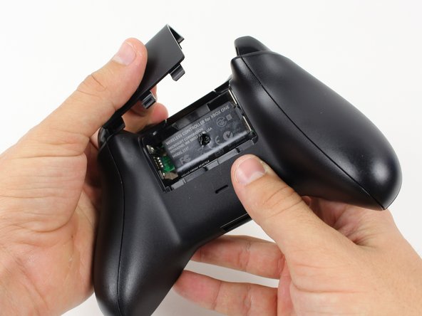
Grip the controller firmly to remove the side handles, wedging a spudger into the seam between the front and handle plates.
-
Pry the side plate away from the front plate by moving the spudger back and forth. You will need to do this all the way around the side plate's seam.
-
-
Este passo não foi traduzido. Ajude a traduzi-lo
-
Use a screwdriver and punch a hole directly in the center of the label.
-
Remove the five 10mm screws located on the back of the controller using the TR8 Security Torx Screwdriver.
-
-
-
Este passo não foi traduzido. Ajude a traduzi-lo
-
De-solder the soldered joints while holding the red and black wires down on the top motherboard.
-
De-solder the black and gray wires that are attached to the top motherboard.
-
Remove the rumble motors and set them aside.
-
-
Este passo não foi traduzido. Ajude a traduzi-lo
-
Unscrew the two 7mm T6 screws located near the rumble motor sockets.
-
-
Este passo não foi traduzido. Ajude a traduzi-lo
-
Firmly grip sides of motherboard near the middle.
-
Lift upwards while slightly wiggling the motherboard forward and backward.
-


Cancelar: não concluí este guia.
28 outras pessoas executaram este guia.
Equipe

Cal Poly, Team 20-15, Maness Winter 2015 Membro de Cal Poly, Team 20-15, Maness Winter 2015
CPSU-MANESS-W15S20G15
Membros da 5
Autoria de 50 guias
6 comentários
I was only able to unscrew 2 of the Torx screws. They have a pin right in the middle that doesn't allow for the screwdriver to be fully inserted, or at all. The two screws I was able to unscrew must've had a shorter pin than the others.
These points on the head is what we call a security torx screw. You will need the specific T8 or T6 Security Torx Screwdriver to remove these screws.
You can use a small flat blade screwdriver ;-)
If any of the screws are tight, the centre pin may snap, then you can just use a normal Torx bit.