Esta versão pode conter edições incorretas. Mude para o último instantâneo verificado.
O que você precisa
-
Este passo não foi traduzido. Ajude a traduzi-lo
-
Depress the battery release button on the top of the controller.
-
Remove the battery holder from the controller.
-
-
Este passo não foi traduzido. Ajude a traduzi-lo
-
Use a pair of tweezers to peel the barcode sticker from the battery compartment.
-
-
Este passo não foi traduzido. Ajude a traduzi-lo
-
Remove the seven 9.3 mm T8 Security Torx screws securing the rear case to the front case.
-
-
-
Este passo não foi traduzido. Ajude a traduzi-lo
-
Insert a Spudger between the front and rear cases along the left edge of the controller.
-
Rotate the spudger toward the front of the controller, prying the two cases apart.
-
-
Este passo não foi traduzido. Ajude a traduzi-lo
-
Insert a spudger between the front and rear cases, near the headphone jack.
-
Rotate the spudger toward the front of the controller to pry the two cases apart.
-
-
Este passo não foi traduzido. Ajude a traduzi-lo
-
Grasp the controller by the battery compartment and the headphone jack.
-
Lift the battery compartment away from the headphone jack, separating the rear case from the front case and logic board.
-
-
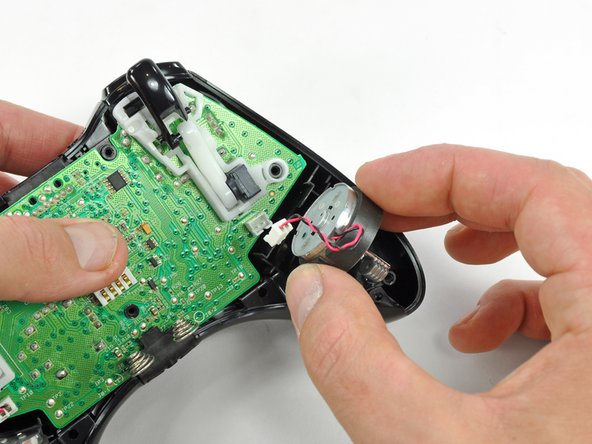
Este passo não foi traduzido. Ajude a traduzi-lo
-
Use the flat end of a spudger to remove the vibration motor cable, moving it upward from its socket on the logic board.
-
Lift the vibration motor out of the front case.
-
-
Este passo não foi traduzido. Ajude a traduzi-lo
-
Remove the vibration motor from the other side of the controller using the same method previously described.
-


Cancelar: não concluí este guia.
19 outras pessoas executaram este guia.


3 comentários
Hello, I am very concerned about which side of the controller the motor with heavier counterweight should be. Shouldn’t it be on the left side of the controller, since the right side should be used for higher frequency vibrations?
Hi Yado,
Thanks for pointing this out! You are right—the left side have the heavier counterweight. I’ve corrected the relevant step.
Hi there, I believe that the screenshots provided have the vibration motors on the wrong sides. Watching several videos of the disassembly on youtube as well as taking apart my own controller that previously was never opened, the larger heavier motor should be on the right side and the smaller lighter motor should be on the left side.