Esta versão pode conter edições incorretas. Mude para o último instantâneo verificado.
O que você precisa
-
Este passo não foi traduzido. Ajude a traduzi-lo
-
Place the Tagital T7X on a sturdy surface.
-
Insert the plastic opening tool into the crack and pry open the tablet. Move the tool along the edge, while continuing to pry up the casing.
-
-
Este passo não foi traduzido. Ajude a traduzi-lo
-
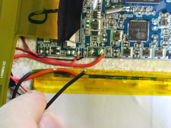
Follow the attached wires to the positive and negative connections.
-
-
Este passo não foi traduzido. Ajude a traduzi-lo
-
Touch the tip of the soldering iron to the solder connecting the negative wire.
-
Pull back on the wire with the iron in place, removing it from the hot solder.
-
Repeat this step for the positive wire.
-
-
Este passo não foi traduzido. Ajude a traduzi-lo
-
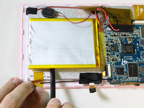
Use the nylon spudger to pry the battery from the back of the screen. Work your way around the edges, similar to opening the casing.
-
-
Este passo não foi traduzido. Ajude a traduzi-lo
-
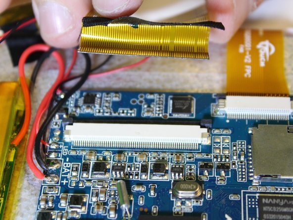
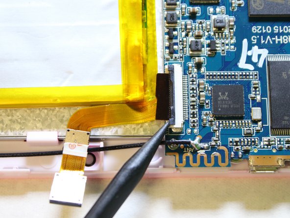
Remove the ribbon cable on the top left corner of the mother board.
-
Gently lift the black tape up to see the ribbon cable socket.
-
-
Este passo não foi traduzido. Ajude a traduzi-lo
-
Push both side buttons away from the socket by using a spudger.
-
-
-
Este passo não foi traduzido. Ajude a traduzi-lo
-
Touch the tip of the soldering iron to the solder connecting the positive (red) wire.
-
Pull back on the wire with the iron in place, removing it from the hot solder.
-
Repeat this step for the negative wire.
-
-
Este passo não foi traduzido. Ajude a traduzi-lo
-
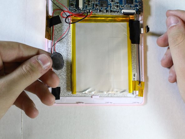
Use a spudger to hold the cameras in place.
-
Gently pull the black tape away using your finger.
-
-
Este passo não foi traduzido. Ajude a traduzi-lo
-
Remove the ribbon cable from the motherboard.
-
Use a spudger to lift the two tabs, freeing the ribbon cable from the socket.
-
-
Este passo não foi traduzido. Ajude a traduzi-lo
-
Gently pull the ribbon cable away from the motherboard.
-
-
Este passo não foi traduzido. Ajude a traduzi-lo
-
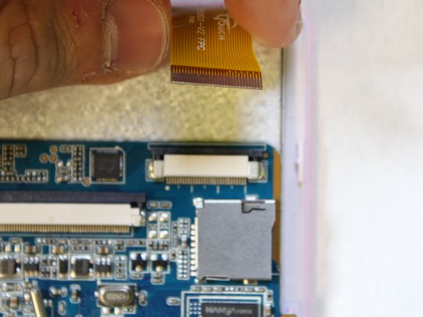
Next we will disconnect the digitizer ribbon cable from the motherboard.
-
Using the black spudger, gently push the tabs on each side of the socket to free the ribbon cable.
-
-
Este passo não foi traduzido. Ajude a traduzi-lo
-
Gently pull on the ribbon cable, separating it from the socket.
-
-
Este passo não foi traduzido. Ajude a traduzi-lo
-
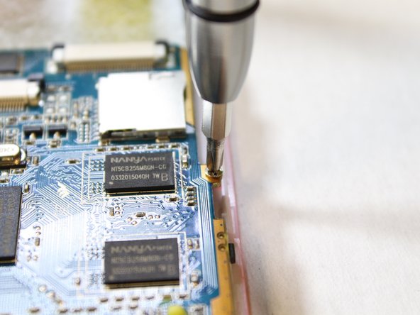
Next, we will unscrew the three PH#0 screws anchoring the motherboard into the case.
-
Using the screwdriver, with the PH#0 attachment, carefully unscrew the screws of the motherboard in order to remove it from the device.
-
-
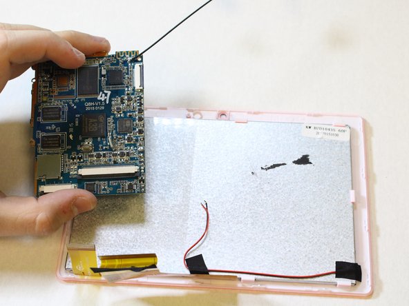
Este passo não foi traduzido. Ajude a traduzi-lo
-
Insert a plastic opening tool where the screen connects with the front face of the case.
-


Cancelar: não concluí este guia.
2 outras pessoas executaram este guia.
Equipe

USF Tampa, Team 2-1, Sullivan Spring 2016 Membro de USF Tampa, Team 2-1, Sullivan Spring 2016
USFT-SULLIVAN-S16S2G1
Membros da 4
Autoria de 12 guias