Esta versão pode conter edições incorretas. Mude para o último instantâneo verificado.
O que você precisa
-
Este passo não foi traduzido. Ajude a traduzi-lo
-
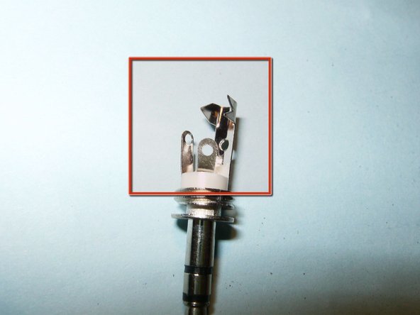
Not very obvious, but the metal plug is actual slightly bend to the left of the picture. There is also some bulging of the plastic around it.
-
After a bit more of a manual inspections, the plug actually just fell out.
-
Use a small set of side cutters to cut the rest of the plug off.
-
-
Este passo não foi traduzido. Ajude a traduzi-lo
-
Use a sharp knife to remove the insulation of the wires. Do it carefully so as to not cut through the wires.
-
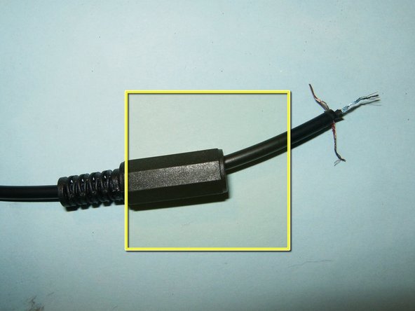
Here are the three wires in the middle of the cable: red, blue, and gold. Now it is time to figure out which wire goes where.
-
Remove the battery by sliding the cover to the right.
-
-
Este passo não foi traduzido. Ajude a traduzi-lo
-
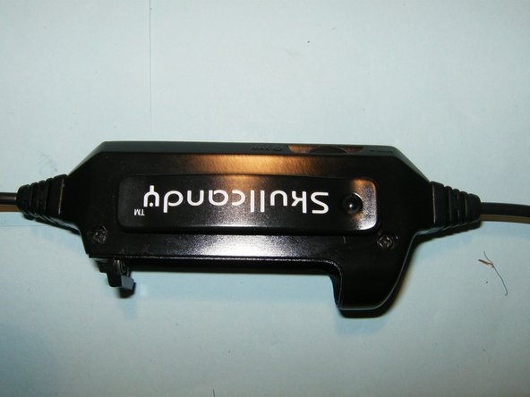
Remove the two Phillips screws. The casing will simply unsnap.
-
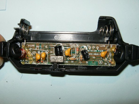
The complete circuit board will be immediately visible.
-
Here is the connector end. Note the wax on the small wires. This is probably to prevent the very small wires from moving too much on the board.
-
-
-
Este passo não foi traduzido. Ajude a traduzi-lo
-
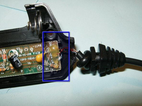
Remove the wax if it is too difficult to identify which wire goes where.
-
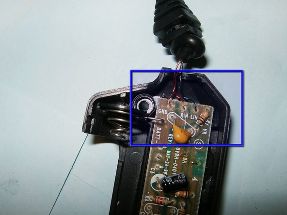
Now the wires can easily be identified. Gold is common ground, red is the right channel, and blue is the left channel.
-
The control box can now be closed again. Apply a few dabs of hot glue over the wires to remove the wax that was previously removed.
-
-
Este passo não foi traduzido. Ajude a traduzi-lo
-
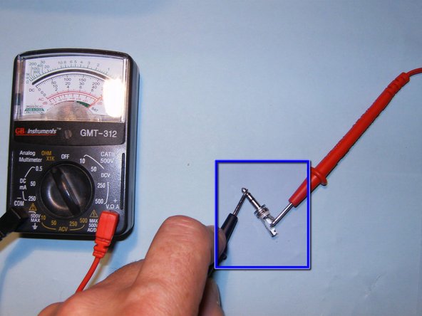
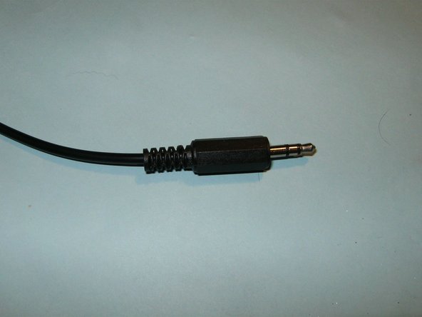
Here is the replacement 3.5mm TRS plug.
-
TRS stands for tip-ring-sleeve, and is the standard connector for audio jacks.
-
The bottom of the jack has three connectors that each correspond to the tip, ring, or sleeve.
-
With one probe constantly on the tip of the jack, probe the three connectors with a multimeter until you have continuity; this is your tip connector.
-
-
Este passo não foi traduzido. Ajude a traduzi-lo
-
Move the stationary probe to the ring terminal and repeat the previous procedure to identify the ring connector.
-
The remaining connector corresponds to the sleeve. In this case, it is the longest connector.
-
Slide the plastic sleeve over the headphone cable. Make sure that it is installed with the larger opening to the wire end.
-
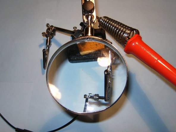
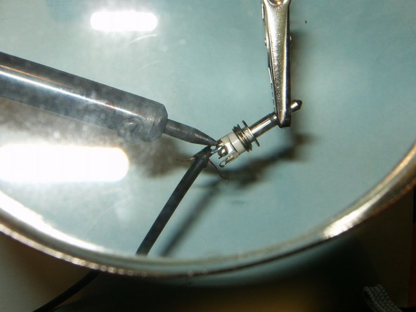
To assist with soldering the small wires, a tool like this third hand is a big help, but not a necessity.
-
-
Este passo não foi traduzido. Ajude a traduzi-lo
-
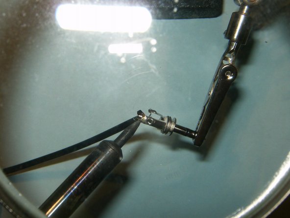
The tip connector on most MP3 players is for the left channel. Solder the blue wire to the tip connector. On this plug it is the shortest one.
-
Solder the red colored wire to the ring (middle) connector
-
Finally solder the gold colored wire to the sleeve (longest) connector.
-
-
Este passo não foi traduzido. Ajude a traduzi-lo
-
Crimp the end of the longest connector over the wire. This will help to prevent the tearing of the solder connection, when the headphones are disconnected by pulling on the cable.
-
Finally attached the cover to the plug.
-
Result is another successful repair accomplished. Sorry oldturkey03 junior, no Dr. Dre this time. Rock on....:)
-


Cancelar: não concluí este guia.
4 outras pessoas executaram este guia.

Equipe

5 comentários
Radio Shack sells them
sir, I want to make this circuit at home. Could you please upload it circuit diagram.
You posted this walk through on my question a week ago now and I just wanted to say thank you. I've completed the repair and my good old skull crushers are as good as new. Though I used a different audio jack then the one in your guide. I instead used a screw fastener type so avoid having to solder since I have zero experience with doing that.
Thanks again!
can you take photos of the amp circuit? i want to make one like that thaks