Esta versão pode conter edições incorretas. Mude para o último instantâneo verificado.
O que você precisa
-
Este passo não foi traduzido. Ajude a traduzi-lo
-
Use a coin to turn the battery locking screw 90 degrees clockwise.
-
Lift the battery out of the computer.
-
-
Este passo não foi traduzido. Ajude a traduzi-lo
-
Remove the following 10 screws:
-
Two 3 mm Phillips in the battery compartment, on either side of the battery contacts.
-
Four 3 mm Phillips around the memory compartment.
-
Four 16 mm Phillips along the hinge.
-
-
Este passo não foi traduzido. Ajude a traduzi-lo
-
Remove the memory compartment cover.
-
Remove the two 12 mm Phillips screws on the Aluminum bracket at the top of the memory compartment.
-
-
Este passo não foi traduzido. Ajude a traduzi-lo
-
Rotate the computer 90 degrees clockwise so the power receptacle faces you.
-
Remove the three 3 mm Phillips screws along the edge of the lower case.
-
-
Este passo não foi traduzido. Ajude a traduzi-lo
-
Turn the computer 90 degrees clockwise so the hinge faces you.
-
Remove the lower 5 mm Phillips screw on each side of the hinge (two total).
-
-
Este passo não foi traduzido. Ajude a traduzi-lo
-
Rotate the computer 90 degrees clockwise so the ports face you.
-
Remove the three 3 mm Phillips screws along the edge of the lower case.
-
When replacing these screws, you must install them in the correct order. Begin by installing the screw closest to the display hinge, then work your way toward the front of the computer. Also, be careful not to put the screws in the two holes on either side of the video out port.
-
-
Este passo não foi traduzido. Ajude a traduzi-lo
-
Turn the computer over and open the display.
-
Remove the two 4.2 mm long, 1.5 mm hex screws at the top corners of the upper case (two total).
-
-
Este passo não foi traduzido. Ajude a traduzi-lo
-
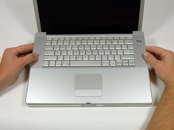
Grasp the back corners of the upper case and pull up.
-
Lift the back of the case up and work your fingers along the sides, freeing the case as you go. Once you have freed the sides, you may need to rock the case up and down to free the front of the upper case.
-
-
-
Este passo não foi traduzido. Ajude a traduzi-lo
-
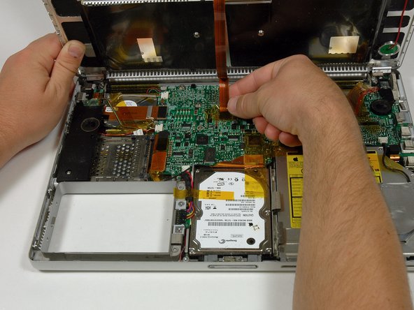
Rotate the upper case up and toward the screen, so that the upper case rests against it.
-
-
Este passo não foi traduzido. Ajude a traduzi-lo
-
Remove the amber tape securing the trackpad ribbon to the logic board.
-
Disconnect the trackpad ribbon from the logic board by pulling up on the connector.
-
Remove the upper case from the computer.
-
-
Este passo não foi traduzido. Ajude a traduzi-lo
-
Remove the 12 mm Phillips screw holding the right speaker assembly to the lower case.
-
-
Este passo não foi traduzido. Ajude a traduzi-lo
-
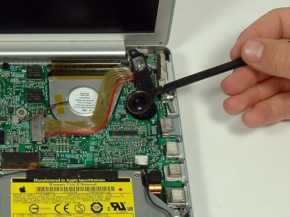
Use a spudger to gently pry the speaker out of its housing.
-
-
Este passo não foi traduzido. Ajude a traduzi-lo
-
Disconnect the hard drive and optical drive connectors from the logic board.
-
Disconnect the right speaker cable connector.
-
De-route the right speaker cable and remove the speaker from the computer.
-
-
Este passo não foi traduzido. Ajude a traduzi-lo
-
Disconnect the 11 remaining cable connectors, removing tape as necessary.
-
-
Este passo não foi traduzido. Ajude a traduzi-lo
-
Remove the following 9 Phillips screws from the logic board:
-
Three 6.5 mm in the upper left corner.
-
Six remaining 4.5 mm.
-
-
Este passo não foi traduzido. Ajude a traduzi-lo
-
Lift up the left side of the logic board enough to disconnect the black and red power cable from the left side of the logic board.
-
While the logic board is lifted, also disconnect the battery connector.
-
-
Este passo não foi traduzido. Ajude a traduzi-lo
-
Remove the single black Phillips screw from the top of the left speaker housing.
-
Remove the 4 mm hex nut from the left speaker housing.
-
Lift the left speaker housing from the lower case and disconnect the microphone/speaker connector.
-
-
Este passo não foi traduzido. Ajude a traduzi-lo
-
Lift the left side of the logic board and disconnect the modem cable from the underside of the logic board. A spudger is useful for freeing the connector from its adhesive.
-
-
Este passo não foi traduzido. Ajude a traduzi-lo
-
Very gently lift up the left side of the logic board.
-
Lift the left edge of the board up to approximately a 30 degree angle (if you don't have your protractor handy, just lift until the DVI port clears the right hinge).
-
Once the logic board clears the ports, slide it out to the left.
-
-
Este passo não foi traduzido. Ajude a traduzi-lo
-
Use a firm plastic edge to scrape the thermal material off the heat sink.
-
Apply a new layer of thermal paste to the heat sink.
-
-
Este passo não foi traduzido. Ajude a traduzi-lo
-
Remove the single silver Phillips screw holding the right speaker housing to the lower case.
-


Cancelar: não concluí este guia.
Uma outra pessoa concluiu este guia.
