Esta versão pode conter edições incorretas. Mude para o último instantâneo verificado.
O que você precisa
-
Este passo não foi traduzido. Ajude a traduzi-lo
-
Flip the laptop over with the screen facing down to reveal the bottom panel.
-
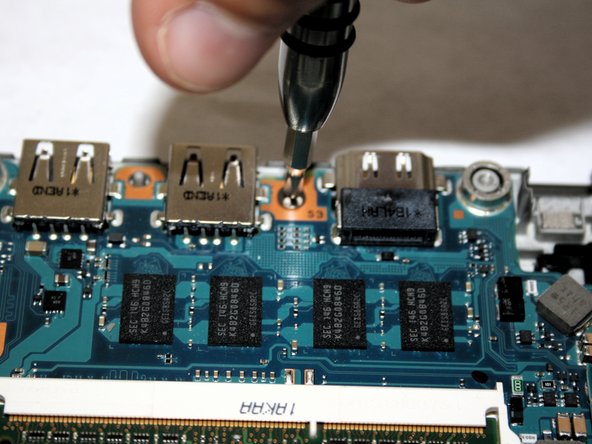
Unscrew each of the highlighted screws with a Phillips #0 screwdriver.
-
-
Este passo não foi traduzido. Ajude a traduzi-lo
-
Use a metal spudger to remove fitting and reveal the screw.
-
Use a screwdriver with a Torx T7 bit to remove the screw.
-
-
Este passo não foi traduzido. Ajude a traduzi-lo
-
The SD Card slot is on the top right corner of the device near the headphone jacks.
-
Depress the fake SD Card and release.
-
Pull the fake SD Card out and remove it completely from the slot, as this will help in the removal of the backplate.
-
-
Este passo não foi traduzido. Ajude a traduzi-lo
-
Lift the back plate starting at the opposing edge to the SD card. Lift from left to right and continue lifting this plate at this angle until it's free from the laptop.
-
Once the backplate is completely off, this will reveal the inside components of the device.
-
-
Este passo não foi traduzido. Ajude a traduzi-lo
-
Remove six 5mm screws holding down the battery using a Phillips PH0 screwdriver.
-
Lift the battery and separate from its place holder.
-
-
Este passo não foi traduzido. Ajude a traduzi-lo
-
Using the nylon spudger, disconnect the white plugin.
-
Once the wire has been disconnected you may remove the battery.
-
-
Este passo não foi traduzido. Ajude a traduzi-lo
-
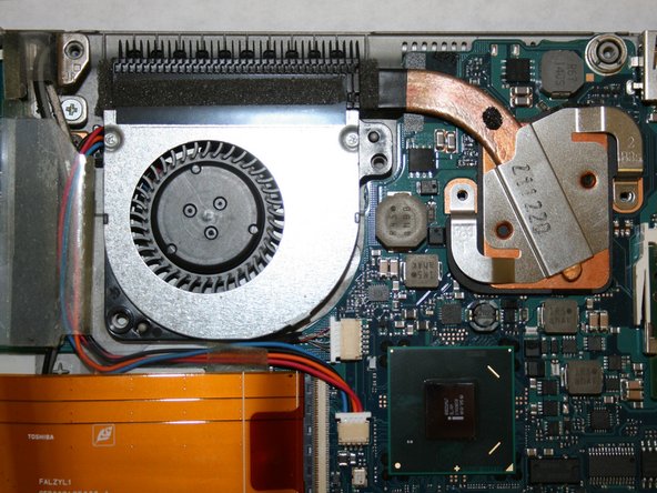
Use a Phillips #0 screwdriver to remove the two 5 mm screws securing the fan.
-
-
Este passo não foi traduzido. Ajude a traduzi-lo
-
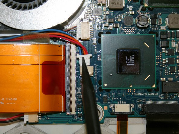
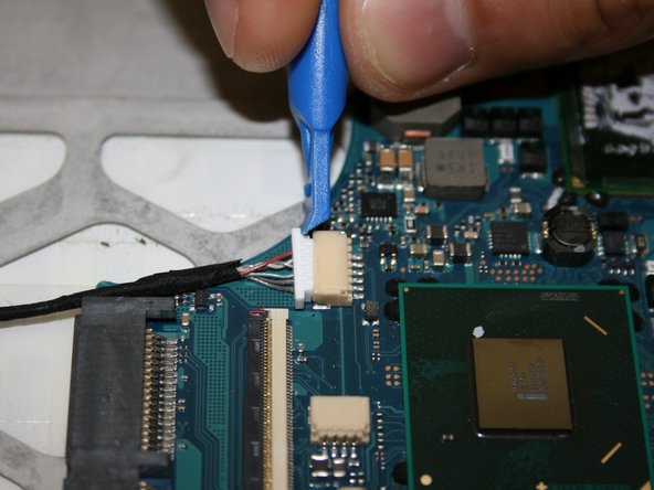
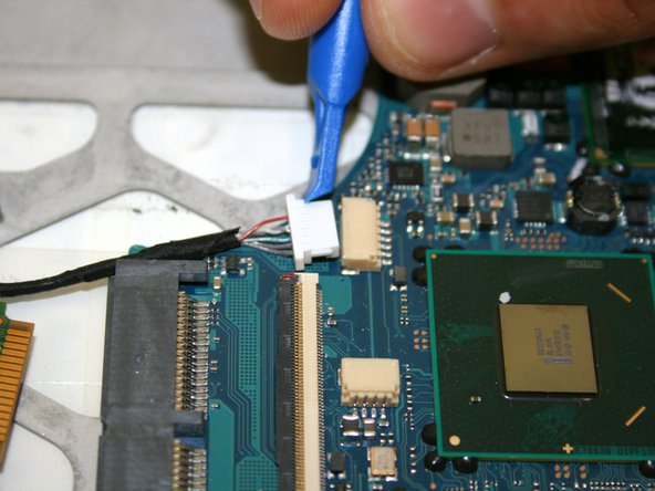
Use a nylon spudger to push the wire (red/blue) plug out of its motherboard port.
-
-
-
Este passo não foi traduzido. Ajude a traduzi-lo
-
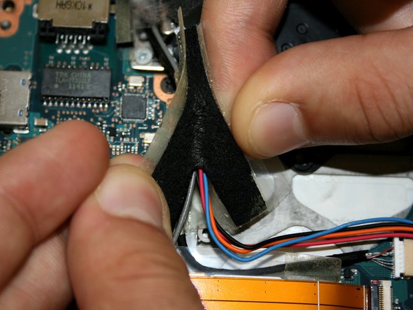
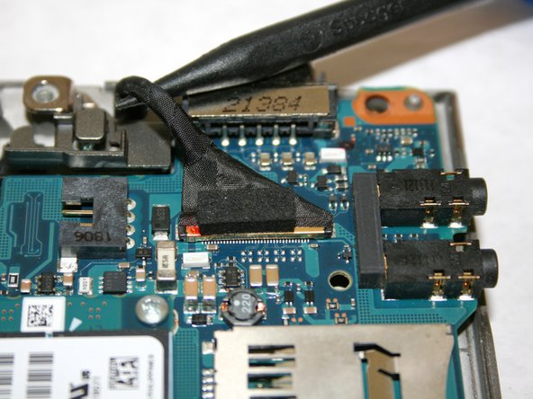
Lift up the wire and peel back the clear protective tape.
-
Split the black protective foam inside the tape in half to uncover the wires.
-
-
Este passo não foi traduzido. Ajude a traduzi-lo
-
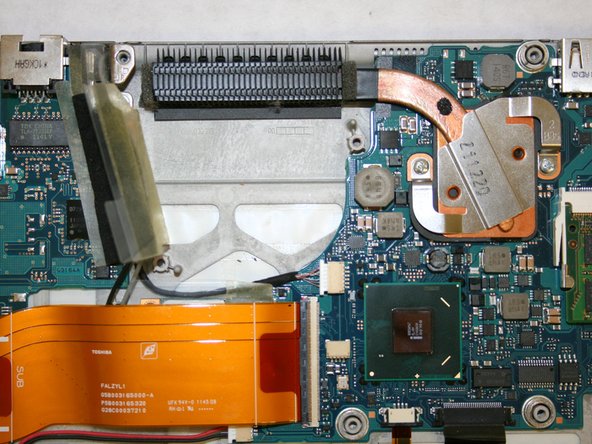
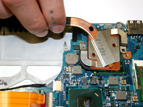
Remove the two 4 mm screws from the heat sink with a Phillips #0 screwdriver.
-
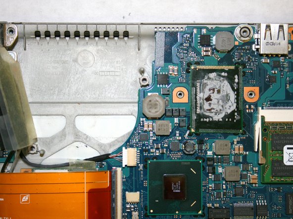
Lift and remove the heat sink from the CPU.
-
-
Este passo não foi traduzido. Ajude a traduzi-lo
-
Use a plastic opening tool to flip up the black lock-bar on the ZIF connector, then disconnect the large orange ribbon cable.
-
-
Este passo não foi traduzido. Ajude a traduzi-lo
-
Remove the single 3 mm screw from the Wi-Fi card with a Phillips #0 screwdriver.
-
Disconnect the Wi-Fi module from the motherboard by gently pulling the card out of its port.
-
-
Este passo não foi traduzido. Ajude a traduzi-lo
-
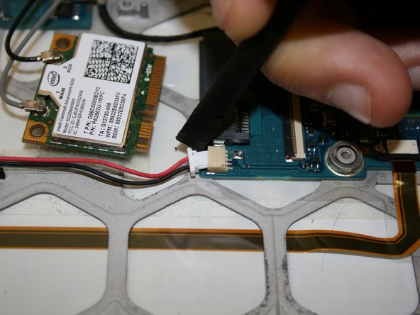
Disconnect the plug from the motherboard using a Plastic Opening Tool.
-
-
Este passo não foi traduzido. Ajude a traduzi-lo
-
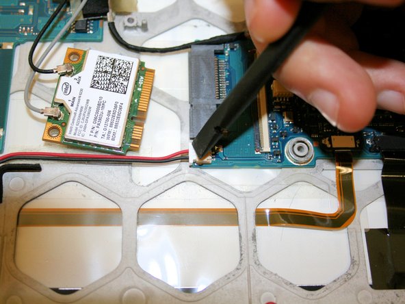
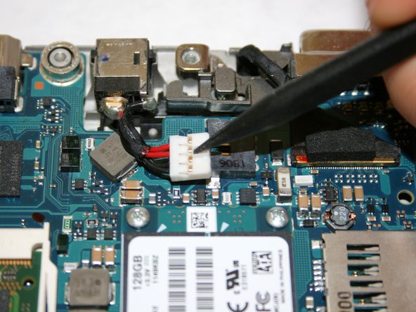
Remove the CMOS battery connector cable (red/black) from its port using a Nylon Spudger Tool.
-
-
Este passo não foi traduzido. Ajude a traduzi-lo
-
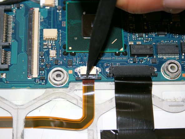
Disconnect the cable from the motherboard using a Nylon Spudger.
-
-
Este passo não foi traduzido. Ajude a traduzi-lo
-
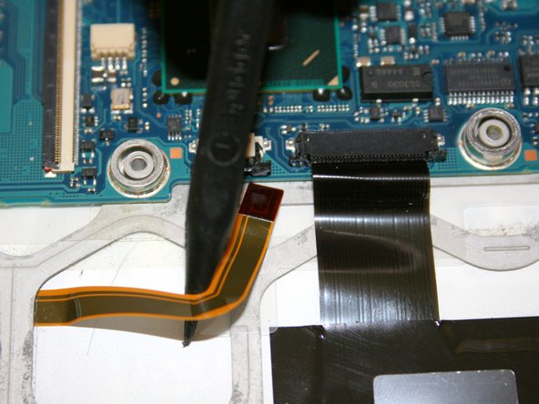
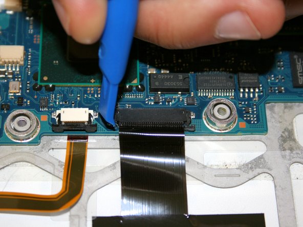
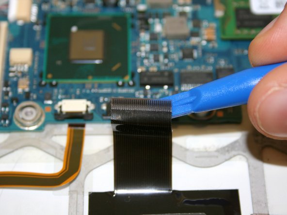
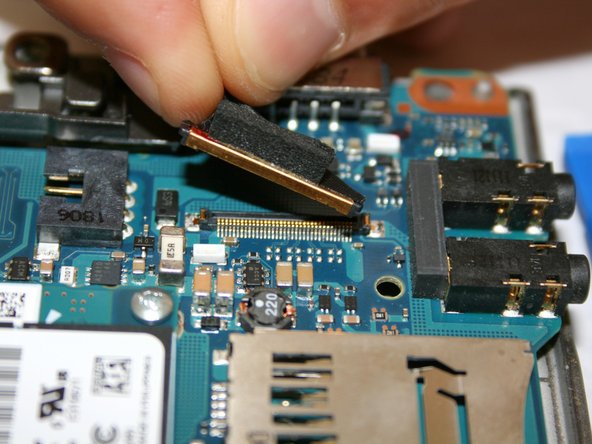
Use a Plastic Opening Tool to disconnect the black ribbon from the motherboard.
-
-
Este passo não foi traduzido. Ajude a traduzi-lo
-
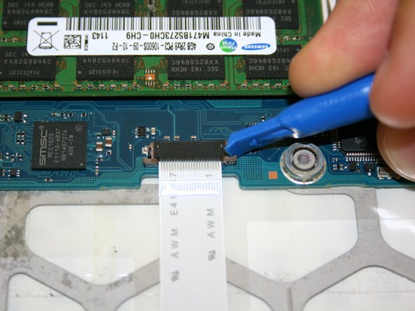
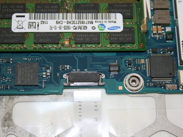
Disconnect the white cable from the port by using a Plastic Opening Tool.
-
-
Este passo não foi traduzido. Ajude a traduzi-lo
-
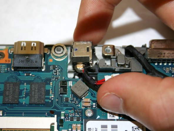
Disconnect the DC power plug connector located at the top of the motherboard using a nylon spudger.
-
Gently remove the whole piece from its holder and place it aside.
-
-
Este passo não foi traduzido. Ajude a traduzi-lo
-
Remove one Phillips #0 3 mm screw from the top of the motherboard.
-
Gently lift the motherboard out of its casing to fully remove it from the device.
-


Cancelar: não concluí este guia.
Uma outra pessoa concluiu este guia.
Equipe

Washington State, Team S2-G7, Hope Fall 2018 Membro de Washington State, Team S2-G7, Hope Fall 2018
WSU-HOPE-F18S2G7
Membros da 3
Autoria de 15 guias