Introdução
The printable files as well as the BOM are available on GitHub. Download the files here.
This guide is for Pangolin PC versions v1.0 and older.
Note: The photos in this guide may not reflect the parts in your version, as the PC in this guide was made with parts from multiple different versions.
O que você precisa
-
-
Before beginning, you must have all the required parts already printed.
 Pergunte ao FixBot
-
-
-
For steps 2-4, you will use the following:
-
1x pangolinpc_base.
-
1x pangolinpc_display_arm.
-
4x M5 screws.
-
-
-
Grab the pangolinpc_display_arm and place it on top of the pangolinpc_base and flip over these pieces.
-
Make sure that the holes outlined match up so you may screw them together.
-
The reason that there isn’t a fourth hole in the third photo is because this is a pre-release prototype. Versions 0.3-alpha and later should have the fourth hole.
-
-
-
Screw in 4x M5 screws into the four holes.
-
-
-
For step 5, you will need the following:
-
The assembly from steps 2-4, which will be referred to now on as the "pangolinpc_base assembly."
-
The Single Board Computer (SBC), which in this case is a Raspberry Pi 5.
-
You will place the SBC in the special slide-in area.
-
Line up the edges of the SBC with the notches in the slide-in area. Then slide the SBC down towards the rear of the pangolinpc_base.
-
-
-
For steps 6-8, you will need the following:
-
1x Webcam cable.
-
The pangolinpc_base assembly.
-
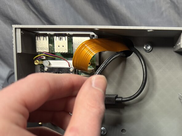
Find the display/camera connectors on the right side of the SBC.
-
You will be plugging the cable into the connector nearest the Ethernet port on the SBC. This port is also labeled "CAM/DISP 0."
-
Pull up the brown clip of the connector.
-
-
-
Insert the cable into the port. Don't force it! They are called "ZIF" (Zero Insertion Force) for a reason!
-
Press down the brown clip to secure the cable.
-
-
-
Insert the fat end of the Webcam cable into the pangolinpc_display_arm and thread it through.
-
Pull the cable out through the top of the pangolinpc_display_arm.
-
-
-
For steps 9-10, you will use the following:
-
1x Micro-HDMI to HDMI cable.
-
The pangolinpc_base assembly.
-
Insert the Micro end into the top of the pangolinpc_display_arm, and thread it through so it comes out inside the assembly.
-
-
-
Insert the cable into the port nearest the USB-C port, marked HDMI0.
-
-
-
For steps 11-12, you will use the following:
-
1x USB-C Power Cable.
-
The pangolinpc_base assembly.
-
-
-
Pull the USB-C cable through the pangolinpc_display_arm.
-
-
-
For steps 13-14, you will use the following:
-
1x Power Strip.
-
The pangolinpc_base assembly.
-
Insert the power strip into the pangolinpc_base, where there is a large hole on the right side.
-
Push the power strip down into the pangolinpc_base until it stops.
-
-
-
In the second photo, this is what your pangolinpc_base should look like inside.
-
-
-
For steps 15-16, you will need the following:
-
1x Anker Power Supply.
-
The pangolinpc_base assembly.
-
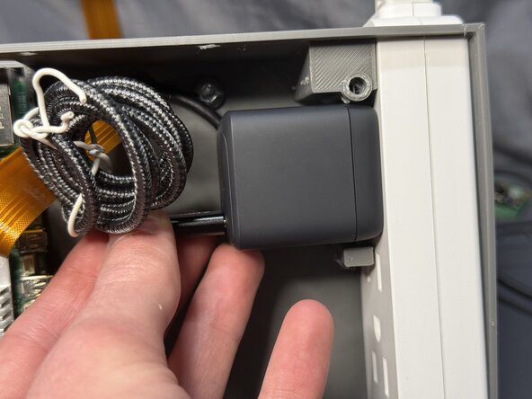
You will be plugging the power supply into the port closest to the rear of the assembly.
-
Plug the power supply into the port.
-
-
-
-
Just like in the last step, make sure the USB-C port is closest to the front of the assembly.
-
Plug the USB-C cable into the power supply.
-
-
-
For steps 17-18, you will need the following:
-
1x Raspberry Pi power supply.
-
The pangolinpc_base assembly.
-
Plug the power supply into the bottom port on the power strip.
-
-
-
You will plug the USB-C cable into the Raspberry Pi's power port.
-
Plug in the cable.
-
-
-
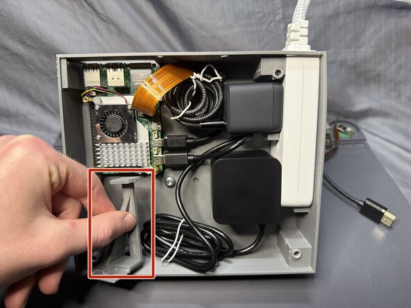
This is what your pangolinpc_base assembly should look like inside.
-
-
-
For step 20, you will need the following:
-
1x pangolinpc_power_button.
-
1x pangolinpc_power_button_assembly_arm.
-
Hot glue.
-
Apply a wave pattern of glue to the pangolinpc_power_button and attach it to pangolinpc_power_button_assembly_arm as shown in the photo.
-
-
-
For step 21-22, you will need the following:
-
The pangolinpc_power_button_assembly_arm assembly.
-
The pangolinpc_base assembly.
-
Hot glue.
-
Install the pangolinpc_power_button_assembly_arm assembly so that the power button is flush where the hole is for the power button on the pangolinpc_base.
-
-
-
Apply hot glue to the areas shown with the red lines.
-
-
-
For step 23-24, you will need the following:
-
2x pangolinpc_plate_legs.
-
1x pangolinpc_base_bottom_plate.
-
Hot glue.
-
You will be gluing the pangolinpc_plate_legs to the rear of the pangolinpc_base_bottom_plate where there are indents.
-
-
-
Install the pangolinpc_base_bottom_plate assembly to the bottom of the pangolinpc_base assembly as shown.
-
-
-
For step 25, you will need the following:
-
2x M5 screws.
-
Screw in the screws into the back holes on the pangolinpc_base assembly.
-
-
-
For step 26-27, you will need the following:
-
2x pangolinpc_plate_legs.
-
2x M5 screws.
-
Hot glue.
-
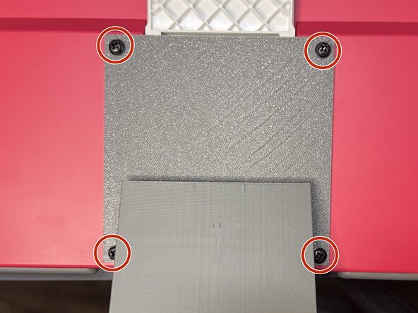
Apply a thin bead of hot glue to the circumference of the screw head, as shown by the red circle.
-
Then place the screw into the pangolinpc_plate_legs so that the bottom of the screw head is flush with the top of the legs.
-
-
-
Install the M5 screw assemblies to the pangolinpc_base assembly.
-
-
-
For steps 28-30, you will use the following:
-
The pangolinpc_vesa_mount
-
4x M5 screws
-
-
-
Thread the HDMI, USB-C, and Webcam cables through the middle square hole in the pangolinpc_vesa_mount.
-
-
-
Screw the four M5 screws in the pangolinpc_vesa_mount, attaching it the pangolinpc_base assembly.
-
-
-
For steps 31-35, you will need the following parts:
-
Raspberry Pi Display.
-
The pangolinpc_base assembly.
-
4x M4 VESA screws.
-
-
-
Flip over the Display.
-
Flip over the white Display stand, making as flush with the back of the Display as possible.
-
-
-
Take the pangolinpc_base assembly and have the power button pointing down, holding the Display arm above the Display's VESA mounting points.
-
Thread the Webcam cable under the white Display stand.
-
Thread it all the way so the end of the cable is sticking out the top end of the Display
-
-
-
Plug the USB-C cable into the Display's USB-C port.
-
Plug the HDMI cable into the Display's HDMI port.
-
-
-
You will be screwing in 4x M4 VESA screws into these four holes on the pangolinpc_vesa_mount.
-
-
-
You're almost done! 🫡👍
-
Take a moment to appreciate your work so far (or go get a coffee or a cookie).
-
-
-
For steps 37-43, you will use the following:
-
1x pangolinpc_webcam_mount.
-
1x pangolinpc_webcam_mount_plate.
-
1x Raspberry Pi Camera Module.
-
2x M5 screws.
-
-
-
Place the Camera Module onto the pangolinpc_webcam_mount_plate, matching up the four pins on the plate with the holes on the Camera Module.
-
-
-
Thread the Webcam cable through the slot near the top of the pangolinpc_webcam_mount.
-
-
-
Unscrew the top two M4 VESA screws holding the Display to the pangolinpc_vesa_mount.
-
Align the bottom two screw holes on the pangolinpc_webcam_mount.
-
Replace the two M4 VESA screws, attaching the pangolinpc_webcam_mount to the pangolinpc_vesa_mount and Display.
-
-
-
This is what the back of your Pangolin PC should look like after Step 40.
-
-
-
Attach the Webcam cable to the Camera Module.
-
Insert the pangolinpc_webcam_mount_plate into the pangolinpc_webcam_mount.
-
-
-
Screw 2x M5 screws into the back of the pangolinpc_webcam_mount.
-


Congrats! You’ve just made your Pangolin PC. If you ran into any hiccups, just open an issue on GitHub here, or if you are feeling adventurous and you think you have a solution, do a Pull Request!
Happy computing!
