Esta versão pode conter edições incorretas. Mude para o último instantâneo verificado.
O que você precisa
-
Este passo não foi traduzido. Ajude a traduzi-lo
-
Using a T5 Torx screwdriver, unscrew the two 5mm screws located at the bottom of the device.
-
-
Este passo não foi traduzido. Ajude a traduzi-lo
-
Peel back the adhesive label below the camera on the rear to reveal a hidden screw, circled in the picture to the left.
-
Alternate Procedure: Underneath the camera, feel for a depression and cut the sticker directly above the depression to reveal the hidden screw.
-
-
Este passo não foi traduzido. Ajude a traduzi-lo
-
Use a #00 Philips screwdriver to remove the 2.5mm hidden screw.
-
-
Este passo não foi traduzido. Ajude a traduzi-lo
-
Use either end of the spudger to carefully pry off the camera lens mesh cover.
-
-
Este passo não foi traduzido. Ajude a traduzi-lo
-
Using the #00 Phillips screwdriver, remove the two 9mm screws on the top corners of the device.
-
-
-
Este passo não foi traduzido. Ajude a traduzi-lo
-
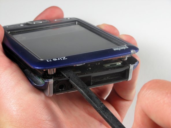
Spin the phone around so that the headphone jack is facing you. Run the flat end of the spudger around the entire edge of the device to gently pry the case off.
-
-
Este passo não foi traduzido. Ajude a traduzi-lo
-
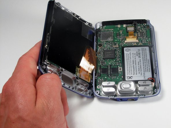
Remove the cover by lifting it from right to left.
-
This should be similar to the action of the opening of a book.
-
-
Este passo não foi traduzido. Ajude a traduzi-lo
-
Lift the control pad buttons off of the motherboard.
-
-
Este passo não foi traduzido. Ajude a traduzi-lo
-
Wedge the flat end of the spudger underneath the battery and gently pry it out.
-
-
Este passo não foi traduzido. Ajude a traduzi-lo
-
Gently disconnect the white component connecting the battery to the motherboard.
-
-
Este passo não foi traduzido. Ajude a traduzi-lo
-
Unscrew the single 3.5mm screw attaching the motherboard to the case with a #00 Phillips screwdriver.
-
-
Este passo não foi traduzido. Ajude a traduzi-lo
-
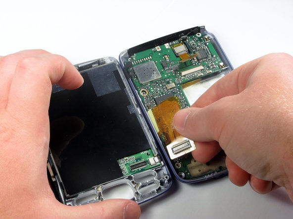
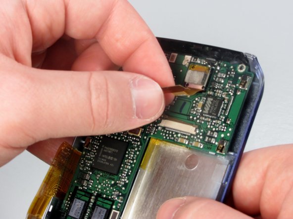
Disconnect the orange video connector leading from the lower case to the upper case with the pointed end of the spudger.
-
The orange video connector is the cable that connects the motherboard to the screen.
-
-
Este passo não foi traduzido. Ajude a traduzi-lo
-
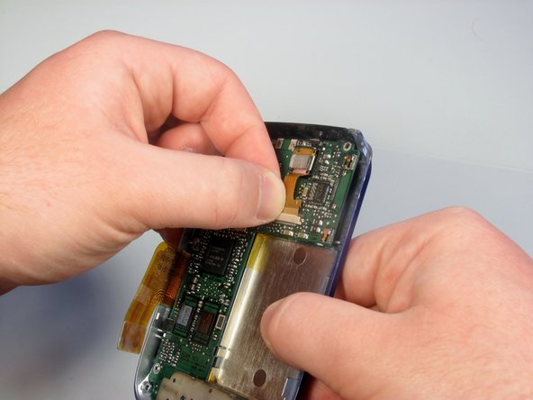
Disconnect the camera from the motherboard. There are 1.5mm gaps on either side of the connector between the connector and its port. Put the pointed end of the spudger in one gap at a time and "walk" the connector out by wedging out the connector on each side.
-
-
Este passo não foi traduzido. Ajude a traduzi-lo
-
Using the spudger, pry the motherboard off of the device.
-
-
Este passo não foi traduzido. Ajude a traduzi-lo
-
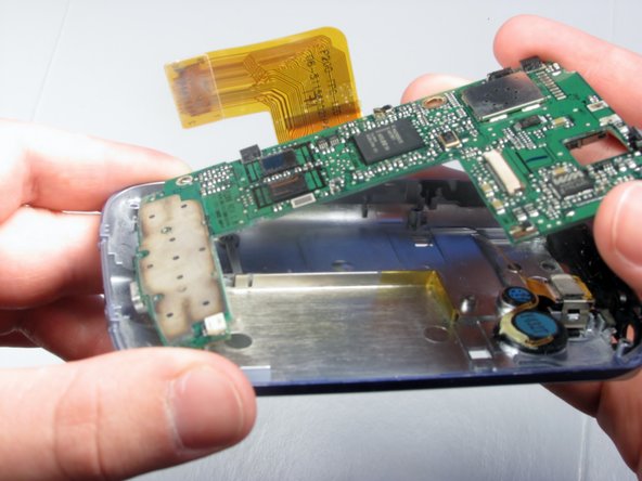
Feed the video connector from the camera through the square hole in the motherboard.
-
After doing so, you may carefully lift the motherboard out of the back case.
-


Equipe

Cal Poly, Team 6-49, Amido Spring 2012 Membro de Cal Poly, Team 6-49, Amido Spring 2012
CPSU-AMIDO-S12S6G49
Membros da 4
Autoria de 11 guias