Esta versão pode conter edições incorretas. Mude para o último instantâneo verificado.
O que você precisa
-
Este passo não foi traduzido. Ajude a traduzi-lo
-
Start by unscrewing the four (4) tri-wing ("Y00")from the back panel.
-
-
Este passo não foi traduzido. Ajude a traduzi-lo
-
Insert an opening pick into the seam at the bottom edge of the controller (opposite the L and ZL buttons).
-
Slowly slide the flat edge of your opening pick up the side of the Joy-Con.
-
-
Este passo não foi traduzido. Ajude a traduzi-lo
-
With the charging rail facing away from you, open the Joy-Con like a laptop.
-
-
Este passo não foi traduzido. Ajude a traduzi-lo
-
Gently pry the battery connector straight up from its socket on the motherboard using a plastic spudger (avoid metal ones to reduce the risk of shorting components). This will keep the Joy-Con from powering on during the repair.
-
-
Este passo não foi traduzido. Ajude a traduzi-lo
-
Insert a spudger between the battery and the Joy-Con housing.
-
Gently pry out the battery.
-
-
Este passo não foi traduzido. Ajude a traduzi-lo
-
Remove the three (3) 3½mm golden Phillips #00 screws from the midframe.
-
-
Este passo não foi traduzido. Ajude a traduzi-lo
-
Carefully flip the midframe over, away from the motherboard, as if you were turning the page of a book.
-
-
-
Este passo não foi traduzido. Ajude a traduzi-lo
-
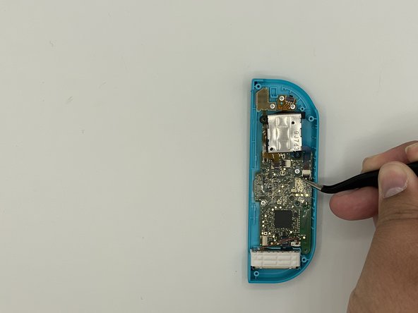
Use tweezers to flip the ZIF connector lock opposite the cable.
-
Use tweezers to gently pull the ZL button flex cable out of its ZIF connector socket. The midframe is now disconnected and can be removed.
-
-
Este passo não foi traduzido. Ajude a traduzi-lo
-
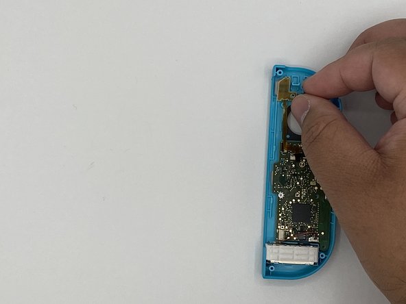
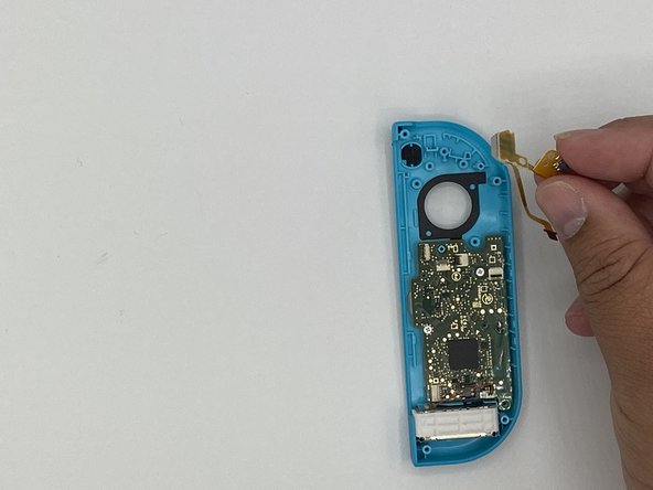
Unlock the rail's top ZIF connector and then disconnect the cable.
-
Unlock the rail's bottom ZIF connector and disconnect the cable. We can now remove the rail from the back frame.
-
Remove the L button and its spring.
-
-
Este passo não foi traduzido. Ajude a traduzi-lo
-
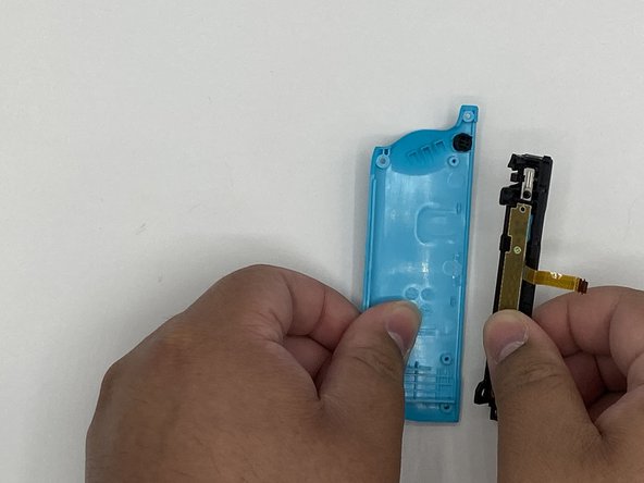
Remove the screw holding the rail in place. Remove the rail from the back frame and set it off to the side.
-
-
Este passo não foi traduzido. Ajude a traduzi-lo
-
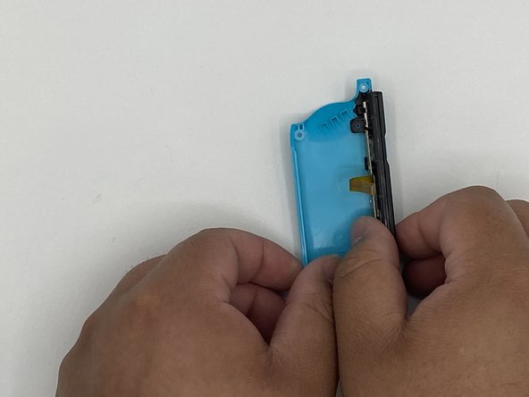
Remove the latch button and set it off to the side.
-
-
Este passo não foi traduzido. Ajude a traduzi-lo
-
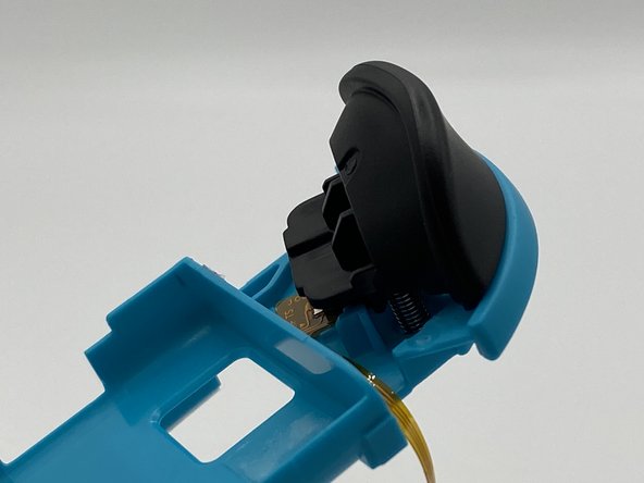
Depress the latch underneath the trigger using tweezers. Gently pry the trigger off.
-
-
Este passo não foi traduzido. Ajude a traduzi-lo
-
Remove the screw holding the circuit board for the trigger in place.
-
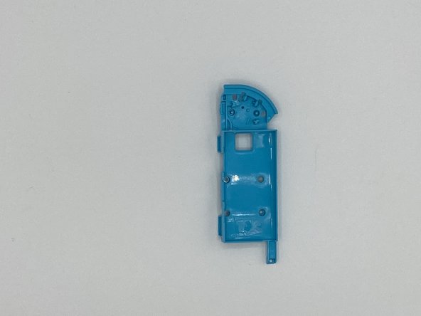
Remove the circuit board.
-
-
Este passo não foi traduzido. Ajude a traduzi-lo
-
Remove the screws holding the joystick in place.
-
Unlock the ZIF connector and remove the ribbon cable using tweezers.
-
-
Este passo não foi traduzido. Ajude a traduzi-lo
-
Remove the screws holding the flex circuit (marked by a red circle) for the minus and L buttons.
-
Remove the flex circuit.
-
-
Este passo não foi traduzido. Ajude a traduzi-lo
-
Remove the screws holding the motherboard in place.
-
-
Este passo não foi traduzido. Ajude a traduzi-lo
-
Using the spudger, gently pry the rumble pack out of its housing.
-
Remove the rumble pack and the motherboard.
-


Cancelar: não concluí este guia.
74 outras pessoas executaram este guia.
Equipe

University of North Texas, Team S1-G12, Raign Spring 2020 Membro de University of North Texas, Team S1-G12, Raign Spring 2020
UNT-RAIGN-S20S1G12
Membros da 2
Autoria de 7 guias
11 comentários
This guide was very helpful! A picture of the latch location on the trigger (step 12) would have been a big help, that step took a minute because I was putting pressure on the wrong spot.
I also noticed that most of the #00 screws were more receptive to a J00 bit. Might be worth noting in the tools section since swapping between them can strip a screw.
Used this guide for reference on the tools needed, someone else pointed out to use the J00 bit instead of the P00 and I’ll second that as the fit for the screws was much better, thanks for the guide much appreciated!
Exactly what I needed! Dropped a set of controllers on a tile flow and the rail popped out and pulled the ribbon cables too. I picked up another iFixit toolkit with some J bits to put it back together. I don’t know why I waited this long to fix it. Charged the controllers overnight and I’m up another set now!
Others above have mentioned that they needed to use a J00 bit instead of P00, but mine did not work with a J00 and was better with a P000
Small thing. In the tools list, it incorrectly says Y0 while the rest of the post correctly says Y00 for the back screws.