O que você precisa
-
Este passo não foi traduzido. Ajude a traduzi-lo
-
Turn over the device.
-
Peel the silicone feet up to remove.
-
-
Este passo não foi traduzido. Ajude a traduzi-lo
-
Remove all eight of the 11 mm Phillips screws from the bottom of the device.
-
-
Este passo não foi traduzido. Ajude a traduzi-lo
-
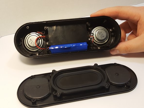
Remove the bottom panel speaker using an iFixit opening tool.
-
-
Este passo não foi traduzido. Ajude a traduzi-lo
-
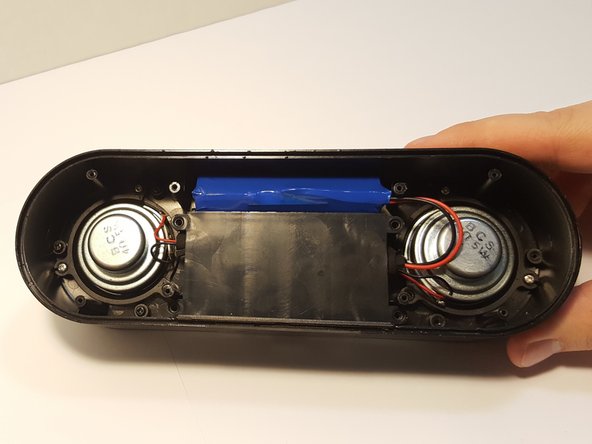
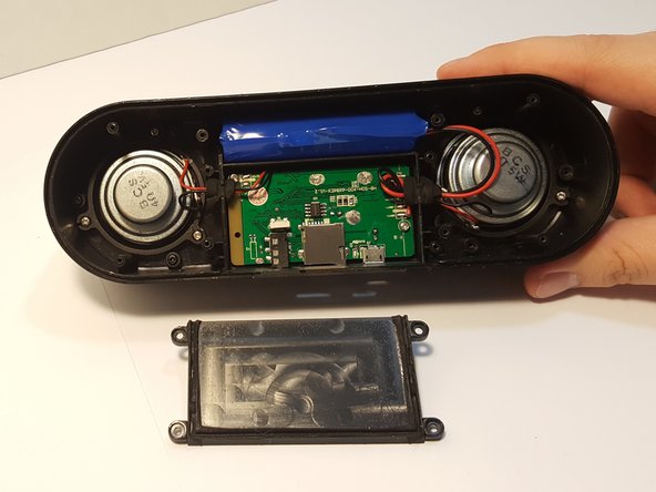
Remove the four 4.5 mm silver Phillips screws that secure the plastic panel covering the motherboard.
-
Remove the plastic panel.
-
-
-
Este passo não foi traduzido. Ajude a traduzi-lo
-
Remove the battery from the holder. It may be difficult the first time.
-
-
Este passo não foi traduzido. Ajude a traduzi-lo
-
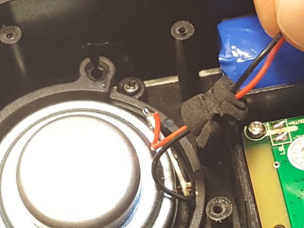
Remove the pressure-fitted foam from the slot by hand.
-
Unravel and remove foam from the wires.
-
-
Este passo não foi traduzido. Ajude a traduzi-lo
-
Using a soldering iron, remove the leads, separating the battery from motherboard.
-
-
Este passo não foi traduzido. Ajude a traduzi-lo
-
Remove the three screws that are holding the speaker down.
-
-
Este passo não foi traduzido. Ajude a traduzi-lo
-
Desolder the speaker joints from the motherboard. Follow this How To Solder guide for help with desoldering.
-
-
Este passo não foi traduzido. Ajude a traduzi-lo
-
Remove the speaker from the motherboard.
-
Remove the speaker ring.
-
Repeat Steps 5-7 with the other speaker.
-
-
Este passo não foi traduzido. Ajude a traduzi-lo
-
Remove these two 4.5 mm Philips silver screws holding down the motherboard.
-
The motherboard should be able to be lifted right out of the housing.
-
-
Este passo não foi traduzido. Ajude a traduzi-lo
-
Using a spudger or plastic opening tool, lift flap on the ribbon cable ZIF connector.
-
Using a plastic pry tool or fine tip plastic tool to open the clamp.
-
Using the tool, try lifting the clamp up on either location, noted by the blue arrow.
-
The ribbon should pop out, if not you should be able to slide it out from the clamp.
-


Cancelar: não concluí este guia.
2 outras pessoas executaram este guia.
Equipe

UMass Dartmouth, Team 3-2, Bhusal Spring 2016 Membro de UMass Dartmouth, Team 3-2, Bhusal Spring 2016
UMASSD-BHUSAL-S16S3G2
Membros da 5
Autoria de 8 guias