Esta versão pode conter edições incorretas. Mude para o último instantâneo verificado.
O que você precisa
-
-
Ligue o Mac e abra o Terminal.
-
Copie e cole o seguinte comando (ou digite-o de forma exata) no Terminal:
-
sudo nvram AutoBoot=%00
-
Pressione [return]. Se solicitado, digite sua senha de administrador e pressione [return] novamente. ''Observação: sua tecla Return também pode se chamar ⏎ ou "enter".
-
sudo nvram AutoBoot=%03
-
-
-
Com uma chave Pentalobe P5, remova os seis parafusos que fixam a estrutura inferior:
-
Dois parafusos de 6,2 mm
-
Dois parafusos de 5,3 mm
-
Dois parafusos de 3,4 mm
-
-
-
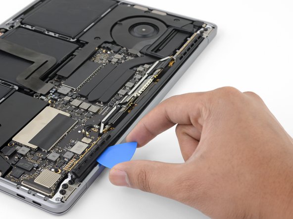
Insira novamente a sua palheta de abertura sob a borda frontal da estrutura inferior, próximo a um dos dois furos mais ao centro.
-
Gire a pinça com firmeza para liberar o terceiro clipe que prende a estrutura inferior ao chassi.
-
Repita esse procedimento próximo ao outro dos dois furos centrais, liberando o quarto clipe.
-
-
-
Retire com cuidado o pedaço grande de fita que cobre o conector da bateria, na borda da placa lógica mais próxima da bateria.
-
Remova a fita.
-
-
-
Este passo não foi traduzido. Ajude a traduzi-lo
-
Remove the four 1.9 mm T3 Torx screws securing the plastic covers on top of the display hinges.
-
Remove both plastic hinge covers.
-
-
Este passo não foi traduzido. Ajude a traduzi-lo
-
Remove the two 2.9 mm T3 Torx screws securing the aluminum cover on top of the main display cable.
-
Remove the cover.
-
-
Este passo não foi traduzido. Ajude a traduzi-lo
-
Remove the two 1.7 mm T3 Torx screws securing the aluminum cover on top of the display cable flex connector.
-
Remove the cover.
-
-
Este passo não foi traduzido. Ajude a traduzi-lo
-
Pry the display board flex cable straight up from its socket to disconnect it from the display board.
-
-
Este passo não foi traduzido. Ajude a traduzi-lo
-
Remove the four 1.5 mm T3 Torx screws securing the two aluminum covers on top of the two display cables.
-
Use a pair of tweezers to remove the two aluminium covers.
-
-
Este passo não foi traduzido. Ajude a traduzi-lo
-
Remove the two 3.3 mm T5 Torx screws (one from each side) securing the antenna cable assembly.
-
Also remove the two 4.1 mm T5 Torx screws (one from each side).
-
Remove the twelve 1.1 mm P2 pentalobe screws (six from each side) securing the rest of the antenna cable assembly.
-
-
Este passo não foi traduzido. Ajude a traduzi-lo
-
Carefully disconnect the two antenna coax cables by prying them straight up from the logic board.
-
Slide your tweezers or spudger underneath each cable until it's near the socket, and then gently twist or pry up to disconnect it.
-
-
Este passo não foi traduzido. Ajude a traduzi-lo
-
Remove the 2.8 mm T5 Torx screw securing the two antenna coax cables to the main board.
-
-
Este passo não foi traduzido. Ajude a traduzi-lo
-
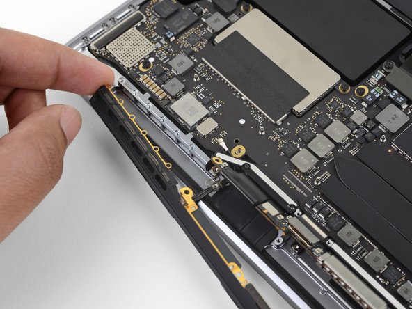
Use an opening pick to lever out the antenna cable assembly in the areas shown.
-
-
Este passo não foi traduzido. Ajude a traduzi-lo
-
Carefully remove the antenna assembly, while simultaneously feeding the antenna cable bundle through the hole in the chassis.
-


Cancelar: não concluí este guia.
Uma outra pessoa concluiu este guia.
