Esta versão pode conter edições incorretas. Mude para o último instantâneo verificado.
O que você precisa
-
Este passo não foi traduzido. Ajude a traduzi-lo
-
Use the flat end of a spudger to disconnect the camera cable connector by prying it straight up from its socket.
-
-
Este passo não foi traduzido. Ajude a traduzi-lo
-
Remove the two screws securing the rear-facing camera bracket:
-
One 3.0 mm standoff screw
-
One 3.1 mm Phillips screw
-
-
Este passo não foi traduzido. Ajude a traduzi-lo
-
Use the point of a spudger to disconnect the flash connector from its socket by prying it straight up.
-
-
Este passo não foi traduzido. Ajude a traduzi-lo
-
Remove the two screws securing the upper cable bracket:
-
One 2.9 mm Phillips screw
-
One 1.3 mm Phillips screw
-
-
-
Este passo não foi traduzido. Ajude a traduzi-lo
-
Use the flat end of a spudger to pry the upper cable connector up from its socket.
-
-
Este passo não foi traduzido. Ajude a traduzi-lo
-
Remove the three Phillips 1.3 mm screws securing the top left antenna component.
-
-
Este passo não foi traduzido. Ajude a traduzi-lo
-
Remove the 1.4 mm Phillips screw securing the antenna component to the top of edge of the case.
-
-
Este passo não foi traduzido. Ajude a traduzi-lo
-
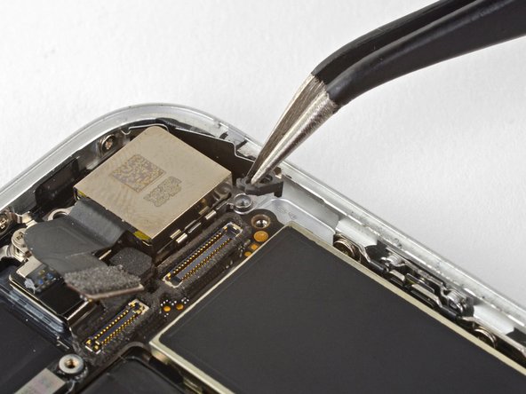
Remove the two Phillips screws securing the grounding clip at the top left edge of the logic board:
-
One 1.5 mm Phillips screw
-
One 2.6 mm Phillips screw
-
-
Este passo não foi traduzido. Ajude a traduzi-lo
-
Remove the three screws securing the motherboard:
-
One 1.8 mm Phillips screw
-
One 2.5 mm standoff screw
-
One 2.2 mm standoff screw
-
-
Este passo não foi traduzido. Ajude a traduzi-lo
-
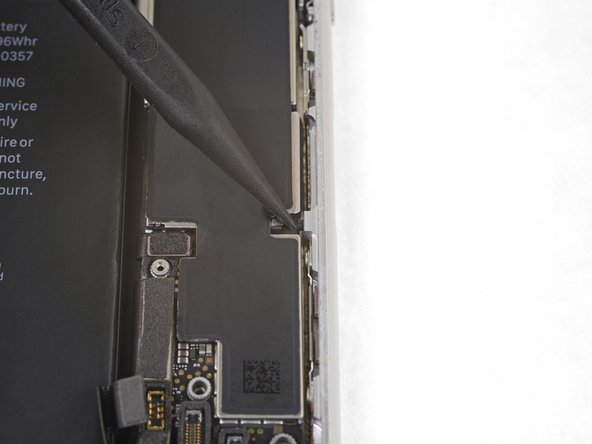
Use tweezers to gently bend the logic board grounding bracket out of the way.
-
-
Este passo não foi traduzido. Ajude a traduzi-lo
-
Use the point of a spudger to move the SIM card eject plunger out of the logic board's way.
-