Esta versão pode conter edições incorretas. Mude para o último instantâneo verificado.
O que você precisa
-
Este passo não foi traduzido. Ajude a traduzi-lo
-
Locate and grab the Water Reservoir with your hands.
-
-
Este passo não foi traduzido. Ajude a traduzi-lo
-
Lift the Water Reservoir up. It should be easy to separate it from the main part of the brewer.
-
-
Este passo não foi traduzido. Ajude a traduzi-lo
-
Remove the Drip Tray by pulling it out of the device.
-
-
Este passo não foi traduzido. Ajude a traduzi-lo
-
Using the Phillips #1 screwdriver, remove the six 140mm screws from the bottom of the Keurig machine.
-
-
Este passo não foi traduzido. Ajude a traduzi-lo
-
Use the metal spudger to separate the silver panel on the right side of the Keurig machine.
-
Tilt the brewer upside down and grab the bottom of the silver panel
-
Using your hands, peel off the silver panel from the Keurig machine.
-
-
-
Este passo não foi traduzido. Ajude a traduzi-lo
-
With one hand, place one finger inside the frame where the silver panel was attached and hold the base.
-
With the other hand, pull down to pop out the front housing of the Keurig machine.
-
-
Este passo não foi traduzido. Ajude a traduzi-lo
-
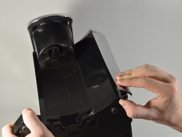
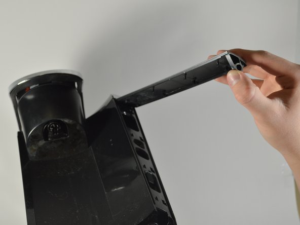
Using your hands, pry the back exterior of the brewer from the right side of the Keurig.
-
Use the blue opening tool to separate the top right silver panel from the back exterior.
-
-
Este passo não foi traduzido. Ajude a traduzi-lo
-
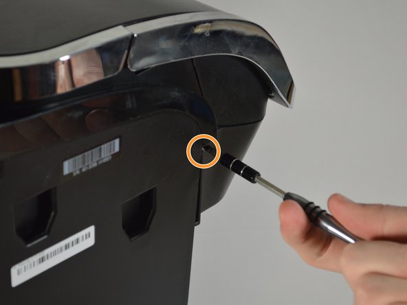
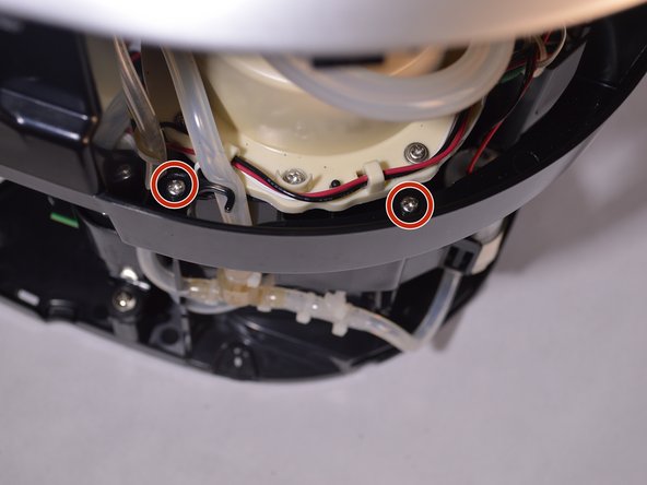
Use the Phillips #1 screwdriver to remove the 120mm screw located on the top left corner from the side of the brewer where the water reservoir was.
-
Use the Phillips #1 screwdriver to remove another 120mm screw located under the end of the empty slot running across the left side of the Keurig.
-
-
Este passo não foi traduzido. Ajude a traduzi-lo
-
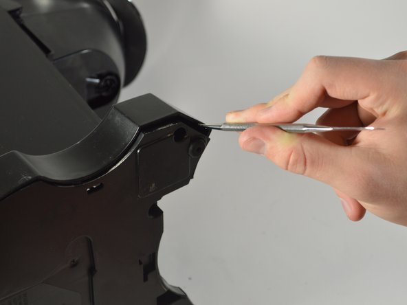
Separate the side panel from the top frame of the brewer, using the blue opening tool for help if necessary.
-
-
Este passo não foi traduzido. Ajude a traduzi-lo
-
Place the brewer on its side as shown in the picture
-
Using the metal spudger, pry away the housing surrounding the sides of the Keurig machine from the bottom.
-
Work your way around the perimeter of the base.
-
-
Este passo não foi traduzido. Ajude a traduzi-lo
-
Remove the entire back exterior surrounding the Keurig by removing the latches connecting the back exterior to the silver frame on top. To do this, use the metal spudger to lift the latches up and out.
-
-
Este passo não foi traduzido. Ajude a traduzi-lo
-
Reorient the brewer as shown in the picture.
-
Locate the four 140mm screws holding the top frame of the Keurig in place. Remove these screws using the Phillips #1 screwdriver.
-
Two of the screws are on the inside of the frame close to the water heater.
-
The other two screws are located on the outside of the frame.
-
-
Este passo não foi traduzido. Ajude a traduzi-lo
-
Remove the top of the framing that encases the circuit board.
-
Remove the wires that are connected to the top of the circuit board.
-
Pull out the multicolored wires by their bases.
-
The bundle with black wires and one red wire is connected to the very top of the circuit board. To remove these wires, squeeze in the white tabs as you pull them out.
-
-
Este passo não foi traduzido. Ajude a traduzi-lo
-
Using the metal spudger, snap the circuit board out of the latches on the bottom of the board.
-
-
Este passo não foi traduzido. Ajude a traduzi-lo
-
Unplug the rest of the wires connecting to the circuit board by pulling them out by their bases.
-
Remove the circuit board from the device.
-


Cancelar: não concluí este guia.
6 outras pessoas executaram este guia.
Equipe

Cal Poly, Team S24-G8, Maness Spring 2018 Membro de Cal Poly, Team S24-G8, Maness Spring 2018
CPSU-MANESS-S18S24G8
Membros da 4
Autoria de 5 guias
5 comentários
Just curious what the phone jack on the bottom is for. There seems to be no mention of this in the user manual.
Weird too that there is a UART mark on the circuit board. Is the coffee maker supposed to ‘phone home’ or obtain firmware updates? I think not.
is there a thermal fuse somewhere?
or if it’s dead, the circuit board?
I'm embarrassed to admit, I forgot which wire goes on which spade connector. :( I know for sure the red wire goes on the middle circuit board spade connector, but now I can't remember if the white wire goes on the top spade connector, or on the bottom corner. Does anyone have a photo of theirs or do you have a clear recollection of whether white is on the top or bottom spade?