Esta versão pode conter edições incorretas. Mude para o último instantâneo verificado.
O que você precisa
-
Este passo não foi traduzido. Ajude a traduzi-lo
-
Remove both end caps by putting a plastic opening tool in the center of the seam. Work around the edges to pry the end caps off completely.
-
-
Este passo não foi traduzido. Ajude a traduzi-lo
-
Turn the Jambox upside down. Peel the indicated rubber tabs off, using a plastic opening tool if necessary.
-
Remove the three T6, 7.0 mm screws under each rubber tab.
-
-
Este passo não foi traduzido. Ajude a traduzi-lo
-
With the Jawbone logo facing towards you and with correct orientation, place the Jambox with the left end cap facing upward.
-
Unscrew indicated T6 9.7 mm screws.
-
Gently loosen the tabs from their anchor points so the bottom may be removed.
-
Flip the Jambox so the other end cap is facing up. The USB cable is on this side (metal grounding clip, indicated in orange). Repeat the above two steps.
-
-
Este passo não foi traduzido. Ajude a traduzi-lo
-
Pry up the bottom panel by lifting from the device.
-
Pull the bottom up. This may take a bit of force as the bottom is glued to device.
-
Once removed, the battery will now be visible.
-
-
Este passo não foi traduzido. Ajude a traduzi-lo
-
Unscrew the eight indicated T6 9.8 mm screws. Remove metal grounding plates.
-
-
Este passo não foi traduzido. Ajude a traduzi-lo
-
Once all eight screws are removed, pry the sides of the Jambox to lift the body from it's shell.
-
-
-
Este passo não foi traduzido. Ajude a traduzi-lo
-
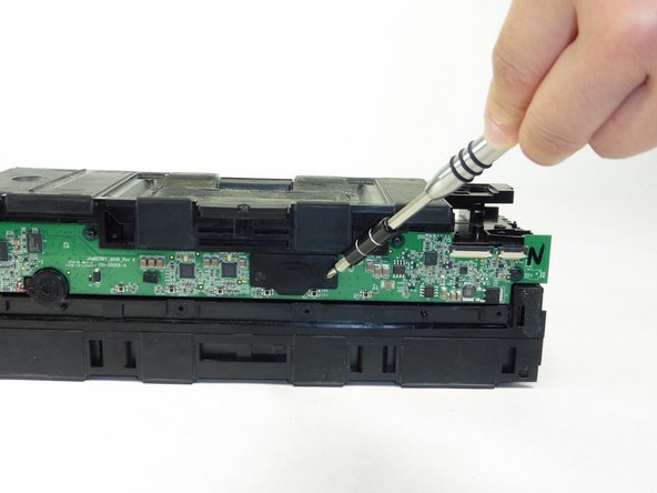
With the battery facing forward, remove the three indicated T6 9.5 mm screws.
-
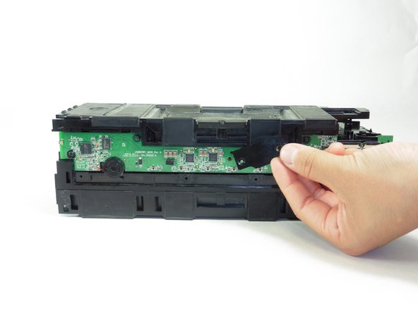
Once the screws are removed, lift up the small plastic plate, revealing the auxiliary board underneath.
-
-
Este passo não foi traduzido. Ajude a traduzi-lo
-
Turn the Jambox so that the button panel is visible.
-
Remove the indicated screws, T6 9.6 mm.
-
-
Este passo não foi traduzido. Ajude a traduzi-lo
-
Remove the colored ribbon that connects the green button circuit board to the blue auxiliary board by using your finger to lift the small black tabs that clamp down the ribbon.
-
-
Este passo não foi traduzido. Ajude a traduzi-lo
-
Place the disassembled Jambox with the speakers facing up.
-
Locate the screws around the broken speaker.
-
Use a T15 screwdriver to remove the four 12.1 mm screws around the broken speaker.
-
-
Este passo não foi traduzido. Ajude a traduzi-lo
-
Using a plastic opening tool, pry the speaker out of the Jambox.
-
-
Este passo não foi traduzido. Ajude a traduzi-lo
-
Desolder the wires from the speaker terminal in the Jambox.
-
-
Este passo não foi traduzido. Ajude a traduzi-lo
-
Remove the two PH0, 5.8 mm screws on the small plastic black panel using a screwdriver.
-
-
Este passo não foi traduzido. Ajude a traduzi-lo
-
Remove the four T6, 9.9mm screws that secure the button circuit board to the body
-
-
Este passo não foi traduzido. Ajude a traduzi-lo
-
Minding the small L-shaped piece of metal on the end opposite of the ports, lift the circuit board from the body of the Big Jambox.
-


Cancelar: não concluí este guia.
3 outras pessoas executaram este guia.
Equipe

Cal Poly, Team 24-5, Lancaster Spring 2015 Membro de Cal Poly, Team 24-5, Lancaster Spring 2015
CPSU-LANCASTER-S15S24G5
Membros da 4
Autoria de 9 guias