Ir para o conteúdo principal

Flash Motherboard

O que você precisa

  1. Flash Motherboard, Front and Back Covers: passo 1, imagem 1 %32 Flash Motherboard, Front and Back Covers: passo 1, imagem 2 %32 Flash Motherboard, Front and Back Covers: passo 1, imagem 3 %32
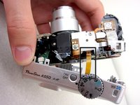
    • Unscrew a total of 6 4.45 mm phillips head screws using a #00 phillips head screwdriver.

    • There are 2 screws on the left side (when looking at the front of the camera).

    • There are 3 screws on the bottom

    • There is 1 screw on the right side

  2. Flash Motherboard: passo 2, imagem 1 %32
    • Turn to the bottom of the camera.

    • Open the memory card cover by sliding the "CARD/BATT." button up, and then pulling the cover to the left.

  3. Flash Motherboard: passo 3, imagem 1 %32
    • This is what the SD card/battery compartment looks like when opened.

    • Remove one 4.45mm phillips head screw from the SD card/battery compartment using a #00 phillips head screwdriver.

  4. Flash Motherboard: passo 4, imagem 1 %32 Flash Motherboard: passo 4, imagem 2 %32
    • Gently remove the front cover away from the camera body.

    • Tip: Start by loosening the teeth on the left side of the camera next to the battery compartment.

  5. Flash Motherboard: passo 5, imagem 1 %32
    • The camera should look like this once the front cover is removed.

  6. Flash Motherboard: passo 6, imagem 1 %32 Flash Motherboard: passo 6, imagem 2 %32 Flash Motherboard: passo 6, imagem 3 %32
    • Start from the battery compartment and remove the back cover.

    • Caution: Do not tug on the back cover after it is removed. This could tear the ribbon attaching the back cover to the camera body.

    • Remove the connecting ribbon from the body of the camera using a pair of tweezers.

  7. Flash Motherboard: passo 7, imagem 1 %32
    • Once the ribbon connecting the back cover is removed, the back of the camera body should look like this.

  8. Flash Motherboard, Flash Motherboard: passo 8, imagem 1 %32
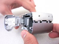
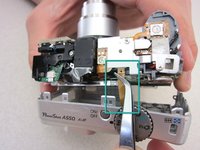
    • Turn to the front of the camera.

    • Find the flash motherboard located behind the flash assembly on the top right.

  9. Flash Motherboard: passo 9, imagem 1 %32
    • Use a soldering iron and a desoldering wick to disconnect the wires from the marked locations.

    • Once the cables are disconnected, you are now ready to install a new motherboard.

Conclusão

To reassemble your device, follow these instructions in reverse order.

3 outras pessoas executaram este guia.

Jakub

Membro desde: 04/19/11

122 Reputação

Autoria de 2 guias

Equipe

Cal Poly, Team 8-6, Regan Spring 2011 Membro de Cal Poly, Team 8-6, Regan Spring 2011

CPSU-REGAN-S11S8G6

Membros da 4

Autoria de 22 guias

0 comentários

Adicione um comentário

Exibir estatísticas:

Últimas 24 horas: 0

Últimos 7 dias: 2

Últimos 30 dias: 13

Duração total: 3,729