Esta versão pode conter edições incorretas. Mude para o último instantâneo verificado.
O que você precisa
-
Este passo não foi traduzido. Ajude a traduzi-lo
-
Locate RAM access panel located on the bottom of the Compaq Armada.
-
Locate and remove the one screw using the T9 Torx Screwdriver.
-
Remove RAM access panel.
-
-
Este passo não foi traduzido. Ajude a traduzi-lo
-
Lift protective covering to reveal the RAM.
-
The RAM sockets lack a locking mechanism. Remove the RAM by applying firm and even pressure, pulling the Ram directly from their sockets.
-
-
Este passo não foi traduzido. Ajude a traduzi-lo
-
Locate and remove the 10 screws found on the bottom of the laptop using the 3.0 mm Flathead Screwdriver.
-
-
Este passo não foi traduzido. Ajude a traduzi-lo
-
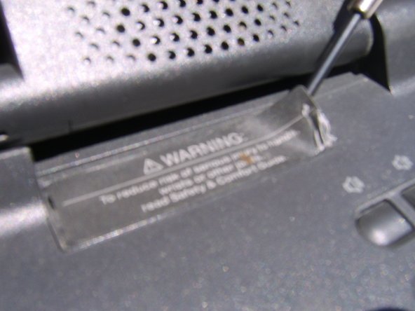
Locate the Warning Label near the top right corner of the Keyboard.
-
Use the flat end of the Spudger to carefully peal away the Warning Label.
-
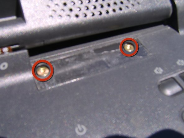
Remove the two screws revealed beneath the Warning Label using the T9 Torx Screw Driver.
-
-
Este passo não foi traduzido. Ajude a traduzi-lo
-
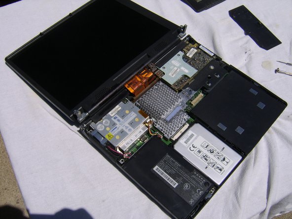
Carefully lift the Keyboard free, raising it directly up and off of the laptop.
-
-
Este passo não foi traduzido. Ajude a traduzi-lo
-
Locate Battery in the bottom left corner of the laptop.
-
The Battery sits freely within the laptop and is easily removed with the gentle application of pressure. Lift gently and pull directly outwards to free it from the Motherboard.
-
-
Este passo não foi traduzido. Ajude a traduzi-lo
-
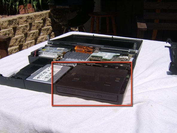
Locate the Disk Drive in the lower right corner of the laptop.
-
The Disk Drive sits freely within the laptop and is easily removed with the gentle application of pressure. Lift gently and pull directly outward to free it from the Motherboard.
-
-
Este passo não foi traduzido. Ajude a traduzi-lo
-
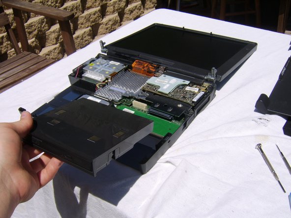
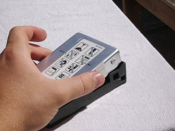
Locate the HDD in the lower center of the laptop, found between the Battery and the Disk Drive.
-
-
Este passo não foi traduzido. Ajude a traduzi-lo
-
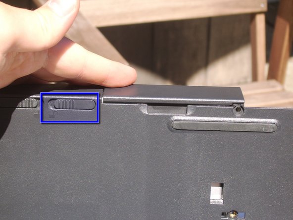
Grasp the frame of the laptop and lift it to a 90 degree angle, revealing the HDD casing's locking mechanism on the bottom of the laptop.
-
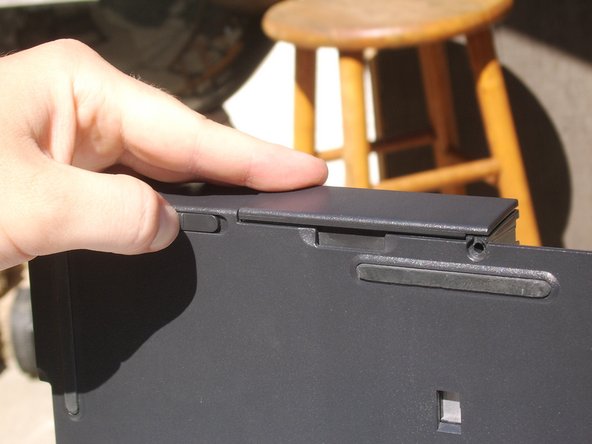
Slide the locking mechanism to the left to free the HDD casing from the laptop.
-
-
-
Este passo não foi traduzido. Ajude a traduzi-lo
-
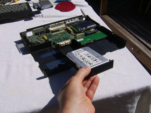
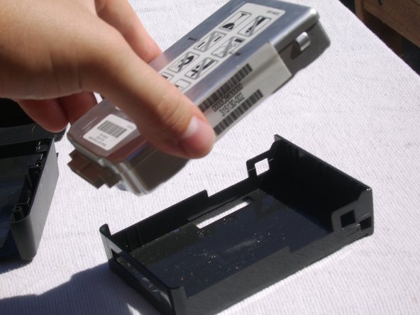
Once the locking mechanism had been released, gently lift and pull the HDD in its casing directly outward.
-
Once free of the Motherboard, grasp the HDD firmly on right and left and lift upwards at slight angle.
-
Once lifted, pull directly outward at the presented angle to free the HDD from its casing.
-
-
Este passo não foi traduzido. Ajude a traduzi-lo
-
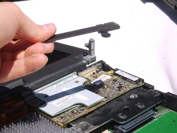
Locate and remove the single screw from Audio Driver's locking bar using the T9 Torx Screwdriver.
-
Gently free the locking bar from the Audio Drivers.
-
And lift it away.
-
-
Este passo não foi traduzido. Ajude a traduzi-lo
-
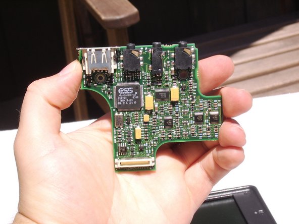
Once the guard has been removed, the upper Audio Drive sits freely on the lower Audio Drive.
-
Firmly grasp the upper Audio Drive on both sides and lift directly and evenly upwards to free it from the lower Audio Drive.
-
-
Este passo não foi traduzido. Ajude a traduzi-lo
-
Locate the protective plastic sheet which sits between the upper and lower Audio Drives.
-
Lift to remove the protective plastic sheet.
-
The lower Audio Drive remains.
-
-
Este passo não foi traduzido. Ajude a traduzi-lo
-
Locate the small ribbon cable connecting the Audio Drive to the Display casing, found at the top left corner of the Audio Drive.
-
Grasp the cable by its plastic cover and lift directly upwards to free it from the Audio Drive.
-
-
Este passo não foi traduzido. Ajude a traduzi-lo
-
Locate and remove the one screw from the lower right of the Audio Drive using the T9 Torx Screwdriver.
-
Lift the Audio Drive up and gently to the left to free it from the Motherboard.
-
-
Este passo não foi traduzido. Ajude a traduzi-lo
-
Locate and remove the one screw from the upper right of the Audio Driver's seat using the T9 Torx Screwdriver.
-
Locate and remove the one screw from the middle left of the Audio Driver's seat using the 2.4 mm Flathead Screwdriver.
-
Lift the Audio Driver's seat directly up to remove it from the Motherboard.
-
-
Este passo não foi traduzido. Ajude a traduzi-lo
-
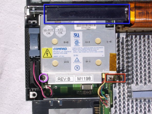
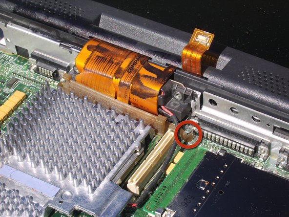
Locate and remove the one screw from the lower left of the Power Supply using the 2.4 mm Flathead Screwdriver.
-
Locate and remove the two screws from the metal guard anchoring the lower right side of the Power Supply using the 3.0 mm Flathead Screwdriver.
-
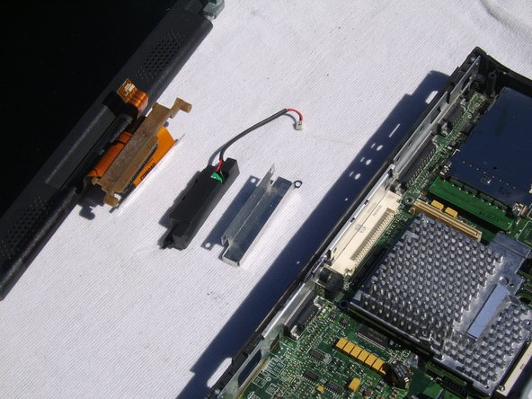
Remove metal guard.
-
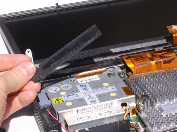
Locate plastic guard along the top of the Power Supply.
-
From the far right lower corner, tilt the plastic guard upwards and lift free of the Power Supply.
-
-
Este passo não foi traduzido. Ajude a traduzi-lo
-
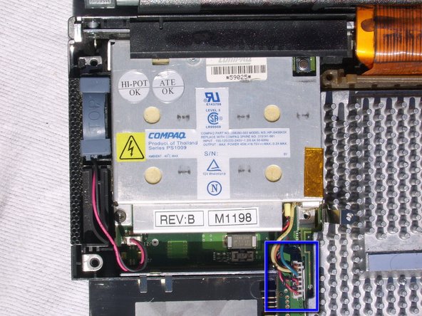
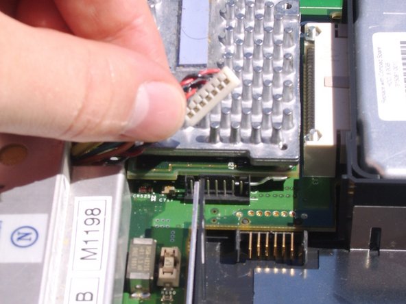
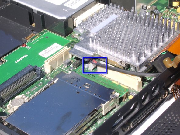
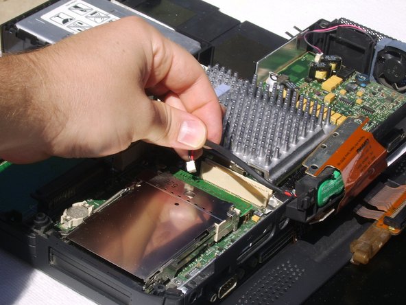
Locate the cable connecting the Power Supply to the Motherboard below the Power Supply on the right.
-
Grasp the cable firmly by its plastic head and pull it free of the Motherboard.
-
-
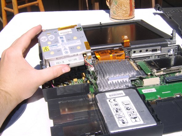
Este passo não foi traduzido. Ajude a traduzi-lo
-
Lift the Power Supply directly up and out of the laptop.
-
-
Este passo não foi traduzido. Ajude a traduzi-lo
-
Close the screen of the laptop and turn the device so you can see its back.
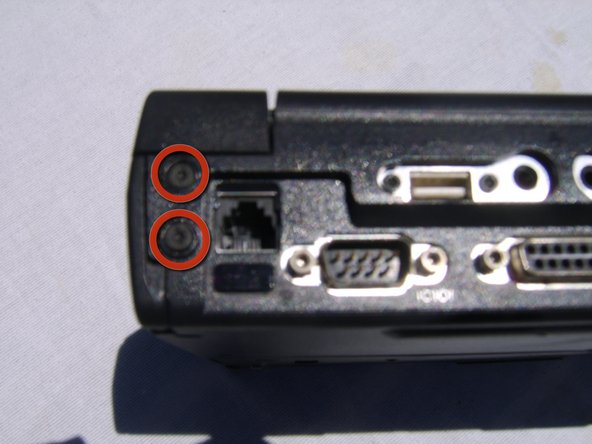
-
Locate and remove the two screws located on the back of the laptop on its left side using the 3.0 mm Flathead Screwdriver.
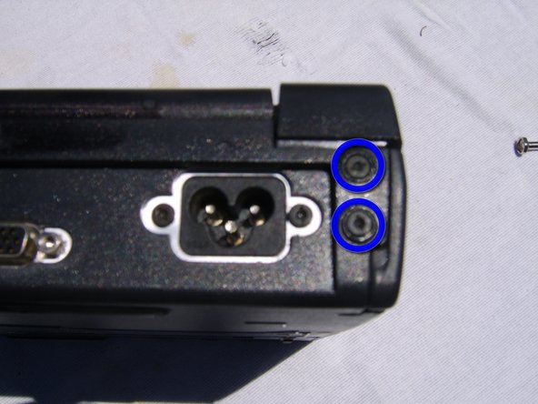
-
Locate and remove the two screws located on the back of the laptop on its right side using the 3.0 mm Flathead Screwdriver.
-
-
Este passo não foi traduzido. Ajude a traduzi-lo
-
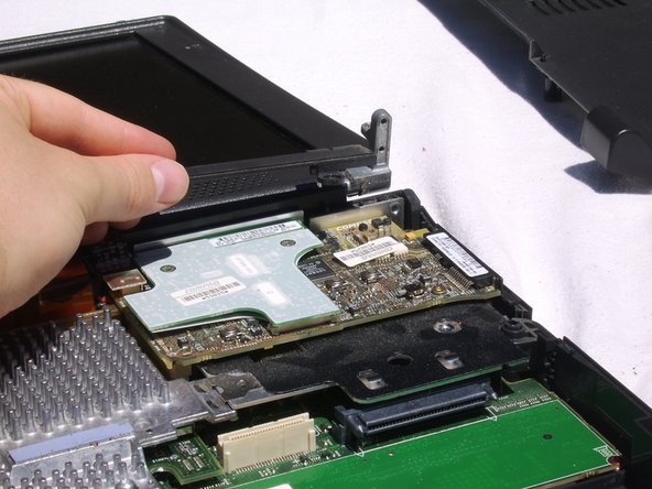
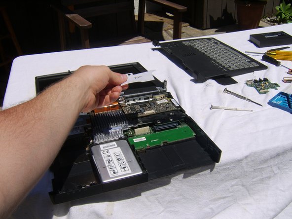
Turn the laptop back over and carefully lift the Display and its metal anchors clear of the laptop. Angle the metal anchors safely away from the Motherboard as shown.
-
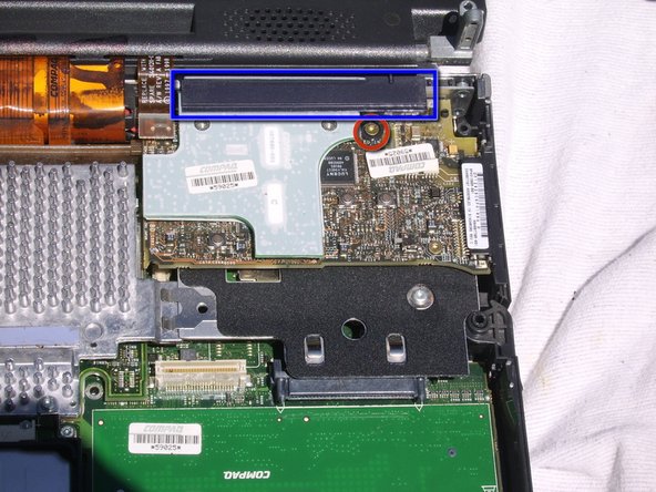
Locate and remove the one screw from the far right of the ribbon cable attaching the Display case to the Motherboard using the 2.4 mm Flathead Screwdriver.
-
And pull the ribbon cable free of the Motherboard.
-
-
Este passo não foi traduzido. Ajude a traduzi-lo
-
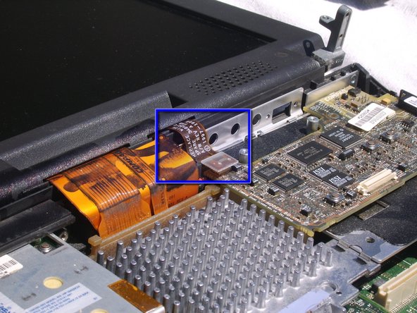
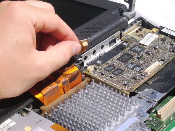
Locate the cable attaching the Display to the Motherboard. It is located between the CPU Board and where the Audio Drivers attach.
-
Firmly grasp the cable by its plastic head and pull it free of the Motherboard.
-
Lift the Display, the Rechargeable Battery in its casing, and the Rechargeable Battery's metal seat from the Motherboard.
-
-
Este passo não foi traduzido. Ajude a traduzi-lo
-
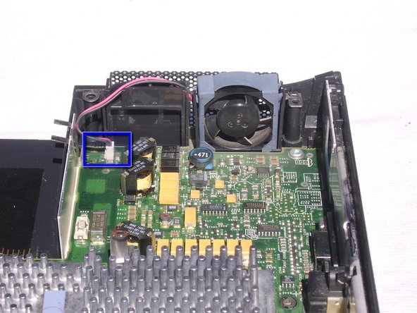
Locate the cable that connects the Power Supply Fan to the Motherboard. Found to the left of the Fan itself.
-
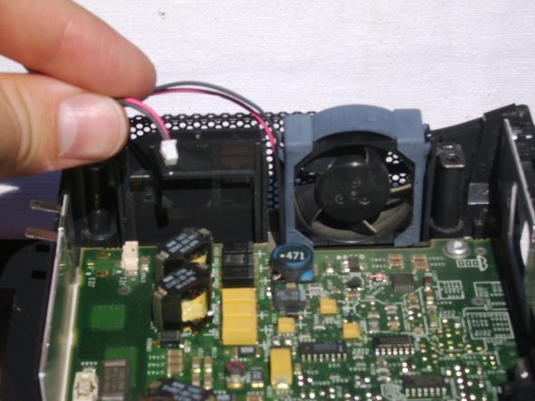
Grasp the cable firmly by its plastic head and pull it free of the Motherboard.
-
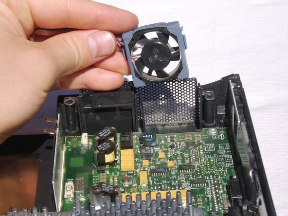
Gently lift the Power Supply Fan free of the laptop. It sits freely in its place and can be removed by lifting it directly upwards.
-
-
Este passo não foi traduzido. Ajude a traduzi-lo
-
Locate and remove the two screws fixing the left metal guard in place using the 3.0 mm Flathead Screwdriver. Remove the metal guard.
-
Perform this step only if you have not already done so in removing the Power Supply.
-
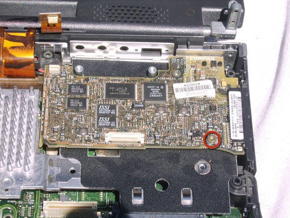
Locate and remove the two screws fixing the bottom right metal guard in place using the 3.0 mm Flathead Screwdriver. Remove metal guard.
-
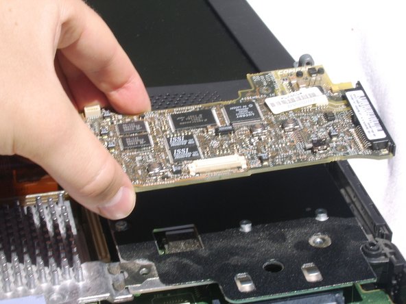
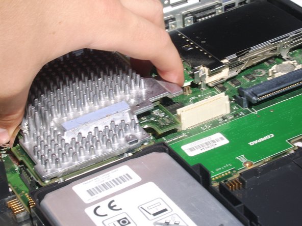
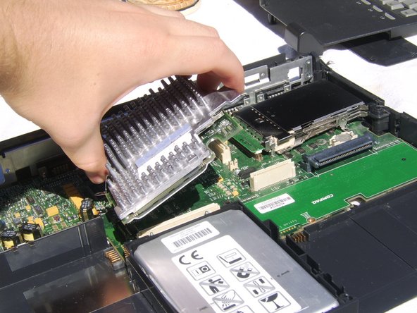
Grasp the CPU Board by the metal tab on the far right.
-
Lift upwards on the metal tab, pulling the CPU Board free of the Motherboard and life upwards to remove it.
-
-
Este passo não foi traduzido. Ajude a traduzi-lo
-
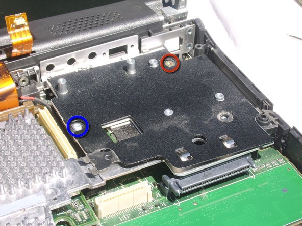
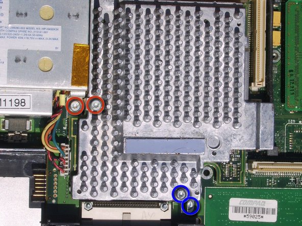
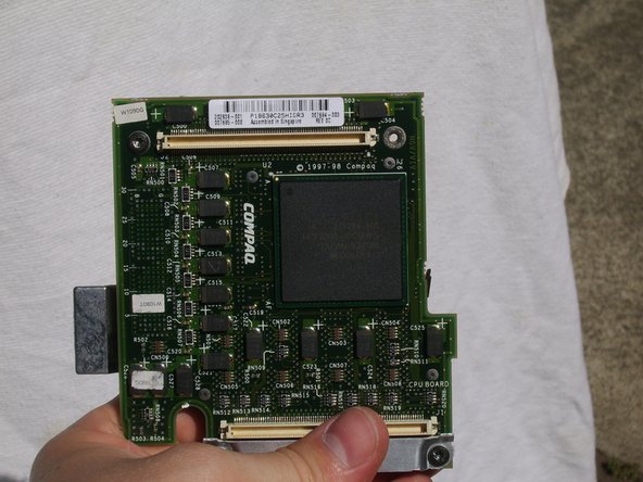
Locate and remove the three screws that fix the metal casing to the CPU Board's under side using the 2.4 mm Flathead Screwdriver.
-
Remove the metal casing.
-
-
Este passo não foi traduzido. Ajude a traduzi-lo
-
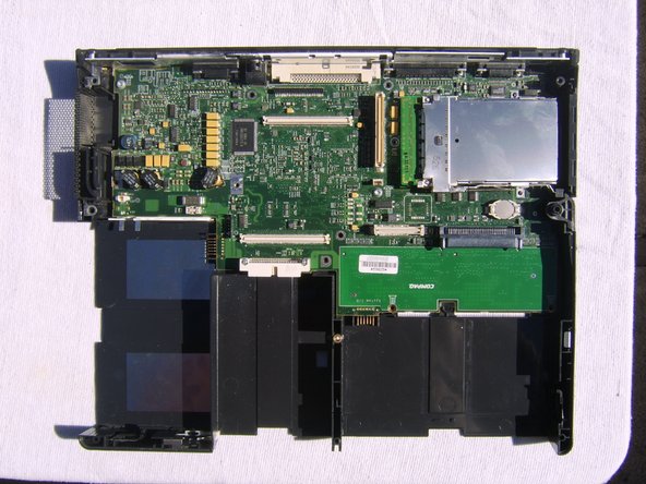
All components have been successfully removed from the Motherboard.
-


Cancelar: não concluí este guia.
7 outras pessoas executaram este guia.