Ir para o conteúdo principal

Esta versão pode conter edições incorretas. Mude para o último instantâneo verificado.

O que você precisa

  1. Este passo não foi traduzido. Ajude a traduzi-lo

    : passo 1, imagem 1 %32 : passo 1, imagem 2 %32 : passo 1, imagem 3 %32
    • Remove the 8, 5.25 mm screws on the back cover using the screwdriver.

    • Carefully remove the back cover using the opening tool.

  2. Este passo não foi traduzido. Ajude a traduzi-lo

    : passo 2, imagem 1 %32 : passo 2, imagem 2 %32 : passo 2, imagem 3 %32
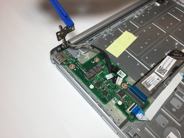
    • Remove the yellow tape from the circuit board that is connected to the USB port.

    • Carefully unplug the two bundled cable connectors by pulling on them.

  3. Este passo não foi traduzido. Ajude a traduzi-lo

    : passo 3, imagem 1 %32 : passo 3, imagem 2 %32 : passo 3, imagem 3 %32
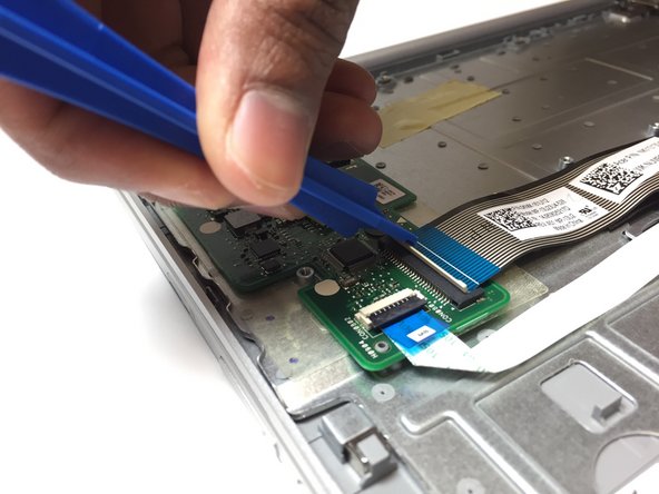
    • Flip up the ZIF connector that holds the larger ribbon cable in place with the opening tool.

    • Carefully unplug the larger ribbon cable by pulling on its blue tab.

  4. Este passo não foi traduzido. Ajude a traduzi-lo

    : passo 4, imagem 1 %32 : passo 4, imagem 2 %32 : passo 4, imagem 3 %32
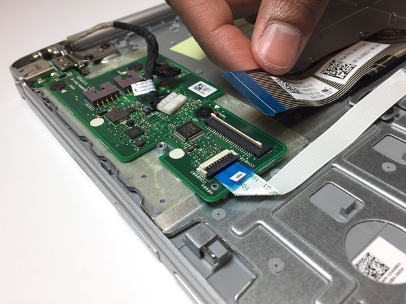
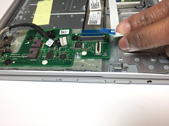
    • Flip up the small ZIF connector that holds the smaller ribbon cable in place with the opening tool.

    • Carefully unplug the smaller ribbon cable by pulling on its blue tab.

  5. Este passo não foi traduzido. Ajude a traduzi-lo

    : passo 5, imagem 1 %32 : passo 5, imagem 2 %32 : passo 5, imagem 3 %32
    • Remove the 3, 2.5 mm screws on the circuit board.

  6. Este passo não foi traduzido. Ajude a traduzi-lo

    : passo 6, imagem 1 %32 : passo 6, imagem 2 %32
    • Remove the 2, 4.25 mm screws on the security tab.

  7. Este passo não foi traduzido. Ajude a traduzi-lo

    : passo 7, imagem 1 %32 : passo 7, imagem 2 %32 : passo 7, imagem 3 %32
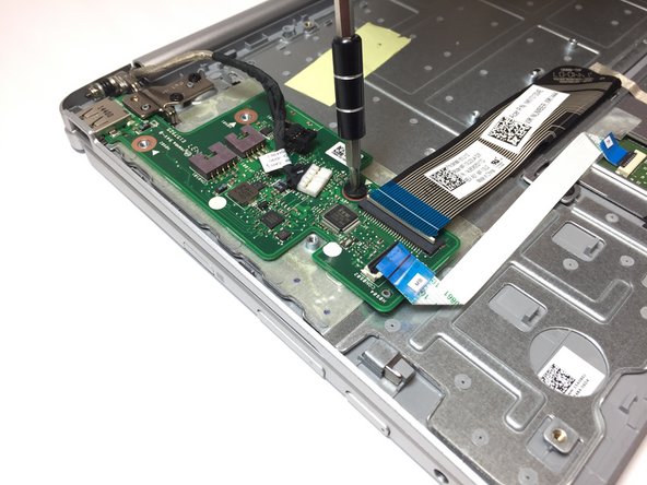
    • Lift the security tab so that it will be out of the way when you remove the circuit board.

    • Using your fingers may be easier than using the opening tool for this particular step, although both can be used.

  8. Este passo não foi traduzido. Ajude a traduzi-lo

    : passo 8, imagem 1 %32 : passo 8, imagem 2 %32 : passo 8, imagem 3 %32
    • Remove the circuit board by lifting it up with the opening tool.

    • The USB port is attached to this circuit board you have just removed. To replace the USB port on this piece, please go to the page How To Solder and Desolder Connections.

Linha de Chegada

Grecia Corrada

Membro desde: 03/19/18

1.134 Reputação

Autoria de 6 guias

Equipe

Baylor, Team S3-G3, Williams Spring 2018 Membro de Baylor, Team S3-G3, Williams Spring 2018

BU-WILLIAMS-S18S3G3

Membros da 3

Autoria de 6 guias

0 comentários

Adicione um comentário

Exibir estatísticas:

Últimas 24 horas: 2

Últimos 7 dias: 6

Últimos 30 dias: 19

Duração total: 1,596