Ir para o conteúdo principal

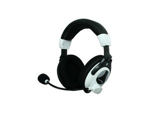
HIgh-end gaming headset manufactured by Turtle Beach.

9 Perguntas Visualizar todos

XBOX Turtle Beach X11 Headset Wires Cut -- Need help with rewiring

I am having an issue with my Turtle Beach X11 headset cables. My cat chewed through the cable today just after the coupler where the 3 wires (USB, Green and Gold) connect. I had to cut off the coupler because the break was too close to get any wire to feed out of. Now I'm looking at 3 sets of wires on one end and 4 separate sets on the other. I've gone through and tried to twist them back separately but I'm not getting power to the remote unit. I've checked the wires for any additional damage down the line and the wires are free of any punctures.

Here's a picture of what the wires do: Wiring Guide

###THREE SEPARATE WIRES BEFORE COUPLER###

When I describe a wire as being insulated with two colors it's not the sheathing that's a different color, there are actually two different colored wires within the sheath.

[USB]

--Gold and Blue copper wires twisted

--Blue{insulated}

[Green Headphone]

--Red{insulated}

--Green{insulated}

--Gold copper wire

[Peach Microphone]

--Red and Gold copper wire twisted

--Blue and Gold wires{insulated}

----------------------------------------------

###MAIN WIRE AFTER COUPLER###

This wire has 4 main wire twists with subsets of wires within each main set. Note: all the wires that are wrapping around insulated wires are exposed to each other.

[1st Wire]

--Blue and Gold copper wire wrapped around

--Blue[insulated]

[2nd Wire]

--Red{insulated}

--Gold copper wire wrapped around the red wire

[3rd Wire]

--Green{insulated}

--Gold copper wire wrapped around the green wire

[4th Wire]

--Blue and Gold{insulated}

--Red and Gold copper wires wrapped around the blue and gold

I've tried connecting just the USB cables to their matching sets and getting power to the control unit but the LED light on the control unit is not coming on. I've also tried just wrapping all 4 exposed sets of wires together but that doesn't help either.

If you have any insight I will be forever greatful.

Thanks.

Respondido! Ver a resposta Também tenho esse problema

Esta é uma boa pergunta?

Pontuação 2
Adicionar um comentário

2 respostas

Solução escolhida

I am unfamiliar with this headset but with deductive reasoning and an understanding of the standards for wiring these devices I will try to help you get this working again. The peculiar thing about this circuit is that there is a monitor for the microphone which means that you are not only talking to somebody, but are also hearing yourself as the same time. Please understand that I do not know how the coupler looks so if you could submit a picture of it, that would be helpful if you need to re-solder directly to the circuit but do not know where it goes. I am also assuming that you know how to solder and that you know about the added effort of soldering audio cables. If you have never soldered before and this is something that you need to have done, you should find someone who knows how or just get a new headset.

Headsets do not usually need to get power, but in this case there is a built in amplifier and since the power needed is not going to come from the audio connection we know that the USB is only serving one purpose. Understanding that the USB connection is only powering the device and not also delivering audio we only need a ground and a hot connection. Seeing as how the gold wire is our common thread we can safely assume this is a grounding lead designed to insulate delicate circuits and improve audio input/output.

The Blue[insulated] will be our hot lead and the wrapped blue and gold will be our grounding wire. That blue wire will be transmitting voltage instead of audio so it wont be the same as the other wires. If you have a multimeter you can plug in the USB and test the cable to make sure it is indeed getting voltage through that wire.

Obviously you should know that if the cables are twisted then they should be left together. That being said lets address what the mystery cables are for. Remember that throughout all of these the gold wire is your grounding wire.

[1st Wire]

It appears to me to be the power source for what would be an electret condenser microphone which just so happen to use the approximate voltage that a USB connection would provide.

[2nd Wire]

The Red insulated cable should be your right speaker.

[3rd Wire]

The Green insulated wire should be the left speaker.

[4th Wire]

The Insulated blue and gold should be microphone. Do not tie this cable together with the the first blue wire. My suspicions are that this is a separated ground lead for the microphone to prevent induction and feedback through tying the ground leads together at that point.

If any of the wrapped cables are touching exposed insulated wire then it can cause a short and prevent the device from working altogether. The light on the coupler is for the microphone which will turn red when the microphone is muted and green when it is not. If you are soldering, the board should have some marking next to the connection to indicate which cable goes where.

There is not much more information that I can provide without images of the damage and not having worked on one myself. Hopefully the information I provided will help you in repairing this microphone. If it makes you feel any better, they are coming out with a wireless version of this microphone soon.

As a last note many people have been able to RMA these microphones for replacements from Turtle Beach.

Esta resposta foi útil?

Pontuação 4
Adicionar um comentário

Just recently fix my headset Turtle Beach P11 because my kids destroyed the 4 pole connector. Took awhile to figure out what went where after dissecting the old connector. There are 6 wires (red, green, blue) all of which are ground wires that is covering a secondary sleeve (Red, Blue, White).

Pin 1 (TIP, Left audio) Red sleeve (burn a little bit of the tip off but do not expose the whole wire.)

Pin 2 (Right audio) Blue sleeve (burn a little bit of the tip off but do not expose the whole wire.)

Pin 3 (Ground) Twist red, green, and blue wires together. Solder to the connection point.

Pin 4 (Mic) White sleeve (pull through the whole on the sleeve. Solder and cut the excess off.)

Esta resposta foi útil?

Pontuação 0

2 comentários:

Thanks for this info Robert! I have the same problem you did.

Where did you get the replacement 4 pole connecter? Do you have a link?

Did you take a picture of it by chance before you sealed it up?

por

I purchased the 4 pole connector from Amazon. I am sorry I did not take a picture before sealing it up. The link below has a diagram of what each point is to assist on where to solder the wires to. It was a bit of a trial and error until I was able to get it to work correctly as I had to use about 2 or 3 to get it to work. My issue was finding out what each color was as many online descriptions was vague or not helpful. Also, trying to prevent shorting out when soldering the wires to the points as the plastic coating is removed during the process.

https://www.amazon.com/gp/product/B077XV...

por

Adicionar um comentário

Adicionar a sua resposta

clint walker será eternamente grato(a).
Exibir estatísticas:

Últimas 24 horas: 0

Últimos 7 dias: 5

Últimos 30 dias: 8

Duração total: 35,463