
Nomenclature
In 2011, the European Automobile Manufacturers Association (ACEA) established the following definitions:
- Socket Outlet: Refers to the port on the electric vehicle supply equipment (EVSE) responsible for supplying charging power to the vehicle.
- Plug: Denotes the end of the flexible cable that connects with the socket outlet on the EVSE. In North America, the socket outlet and plug are not utilized due to the cable's permanent attachment.
- Cable: Describes a flexible bundle of conductors linking the EVSE to the electric vehicle.
- Connector: Represents the end of the flexible cable that interfaces with the vehicle's inlet.
- Vehicle Inlet: Refers to the port on the electric vehicle designed to receive charging power.
The terms electric vehicle connector and electric vehicle inlet were previously defined in a similar manner under Article 625 of the United States National Electric Code (NEC) of 1999. NEC-1999 also outlined electric vehicle supply equipment as the complete unit specifically installed to deliver energy from premises wiring to the electric vehicle, encompassing conductors, electric vehicle connectors, attachment plugs, and all other fittings, devices, power outlets, or apparatuses.
Tesla, Inc. uses the term charging station to describe a location housing a group of chargers, while they refer to an individual EVSE as a connector.
Voltage and Power
NEC
| NEC(1999) levels | |||
| Mode | Maximum Supply | ||
| Current (A) | Voltage (V) | Power (kW) | |
| Level 1 (1-phase AC) | 12 | 120 | 1.44 |
| 16 | 1.92 | ||
| 24 | 2.88 | ||
| Level 2 (1-phase AC) | 32 | 208/240 | 7.68 |
| Level 3 (3-phase AC) | 400 | 480 | 332.6 |
The National Electric Transportation Infrastructure Working Council (IWC) was established in 1991 by the Electric Power Research Institute, comprising members from both automotive manufacturers and electric utilities, with the aim of establishing standards in the United States. Early efforts by the IWC led to the development of three charging levels, as outlined in the 1999 National Electric Code (NEC) Handbook.
In accordance with the NEC-1999, Level 1 charging equipment (as defined in the NEC handbook, although not explicitly in the code) was connected to the grid using a standard NEMA 5-20R 3-prong electrical outlet with grounding. Furthermore, it mandated the inclusion of a residual current device within 12 inches (300 mm) of the plug. The supply circuit was required to have protection at 125% of the maximum rated current. For example, charging equipment rated at 16 amperes continuous current necessitated a breaker sized at 20 A.
Level 2 charging equipment (as specified in the handbook) was permanently wired and securely positioned at a fixed location under NEC-1999. It also demanded grounding and ground-fault protection, in addition to an interlock mechanism to prevent vehicle startup during charging and a safety breakaway for the cable and connector. A 40 A breaker (equivalent to 125% of the continuous maximum supply current) was obligatory for safeguarding the branch circuit. For enhanced convenience and faster charging, many early electric vehicles (EVs) favored the installation of Level 2 charging equipment, which could be connected to the EV through either an inductive paddle (Magne Charge) or a conductive connector (Avcon).
Level 3 charging equipment employed an off-vehicle rectifier to convert the input AC power to DC, which was subsequently supplied to the vehicle. At the time of its authorship, the NEC-1999 handbook foresaw that Level 3 charging equipment would necessitate utilities to upgrade their distribution systems and transformers.
SAE
| SAE J1772(2017) levels | |||
| Mode | Maximum Supply | ||
| Current (A) | Voltage (V) | Power (kW) | |
| AC Level 1 | 12 | 120 | 1.44 |
| 16 | 1.92 | ||
| AC Level 2 | 80 | 208/240 | 19.2 |
| DC Level 1 | 50 - 1000 | 80 | |
| DC Level 2 | 400 | 400 | |
The Society of Automotive Engineers (SAE International) defines the general physical, electrical, communication, and performance requirements for electric vehicle (EV) charging systems used in North America as part of the SAE J1772 standard, initially developed in 2001. SAE J1772 delineates four levels of charging, with two levels each for alternating current (AC) and direct current (DC) supplies. These distinctions are based on power distribution type, standards, and maximum power.
Alternating current (AC)
AC charging stations directly connect the vehicle's onboard charging circuitry to the AC supply.
- AC Level 1: This level connects directly to a standard 120 V North American outlet and is capable of supplying 6–16 A (0.7–1.92 kW), depending on the capacity of a dedicated circuit.
- AC Level 2: It utilizes 240 V (single phase) or 208 V (three phase) power to supply between 6 and 80 A (1.4–19.2 kW), providing a significant increase in charging speed over AC Level 1 charging.
Direct current (DC)
Commonly, though incorrectly, called "Level 3" charging based on the older NEC-1999 definition, DC charging is categorized separately in the SAE standard. In DC fast-charging, grid AC power is converted into DC through an AC-to-DC converter in the station before reaching the vehicle's battery, bypassing any AC-to-DC converter onboard the vehicle.
- DC Level 1: This level supplies a maximum of 80 kW at 50–1000 V.
- DC Level 2: It supplies a maximum of 400 kW at 50–1000 V.
Additional standards released by SAE for charging include SAE J3068, which pertains to three-phase AC charging using the Type 2 connector defined in IEC 62196-2, and SAE J3105, which addresses the automated connection of DC charging devices.
IEC
| IEC 62196 modes | ||||
| Mode | Type | Maximum Supply | ||
| Current (A) | Voltage (V) | Power (kW) | ||
| 1 | 1Φ AC | 16 | 250 | 4 |
| 3Φ AC | 480 | 11 | ||
| 2 | 1Φ AC | 32 | 250 | 7.4 |
| 3Φ AC | 480 | 22 | ||
| 3 | 1Φ AC | 250 | 250 | 57.5 |
| 3Φ AC | 480 | 100 | ||
| 4 | DC | 400 | 600 | 240 |
In 2003, the International Electrotechnical Commission (IEC) incorporated a significant portion of the SAE J1772 standard into IEC 62196-1.
IEC 62196-1 was subsequently revised and expanded into IEC 62196, becoming an international standard encompassing a variety of plug types and charging modes for electric vehicles. This standard is recognized as DIN standard DIN EN 62196 in Germany, ÖVE/ÖNORM EN 62196 in Austria, and SN EN 62196 in Switzerland. It comprises several components that have been gradually adopted. The third part was issued in June 2014, and IEC TS 62196-4, which covers connectors for lightweight electric vehicles, was published in October 2022. Part 1 has reached its fourth edition as of 2022.
The standard follows the IEC 61851 definition for a signal pin responsible for switching the charging current. Notably, the charging station remains voltage-free until an electric vehicle is connected, ensuring that the vehicle cannot be operated during the charging process.
The definitions for the signal pin and IEC-62196-1 charging plugs from Part 1 have been integrated into various technical regulations. In addition to the IEC 60309 "CEEform" three-phase connectors, the charging modes have also been adopted for the SAE J1772 connector in North America (developed by Yazaki), the CHAdeMO connector in Japan, and the Mennekes connector (VDE-AR-E 2623-2-2) in Europe. Each of these connectors serves as the foundation for a network of public charging stations provided by energy providers.
The IEC categorizes charging into modes (IEC 61851-1) as follows:
- Mode 1: This involves slow charging from a standard electrical socket, whether it's single-phase or three-phase AC.
- Mode 2: Slow charging from a regular AC socket, but with specific EV-specific protection arrangements, such as the Park & Charge or PARVE systems.
- Mode 3: This encompasses both slow and fast AC charging, utilizing a particular EV multi-pin socket equipped with control and protection functions, such as SAE J1772 and IEC 62196-2.
- Mode 4: DC fast charging via a dedicated charging interface, like IEC 62196-3, such as CHAdeMO.
The connection between the electric grid and the "charger" (electric vehicle supply equipment) is outlined in three scenarios (IEC 61851-1):
- Case A: Refers to any charger connected to the mains, typically with the mains supply cable attached to the charger itself, primarily associated with modes 1 or 2.
- Case B: Describes an on-board vehicle charger with a mains supply cable that can be detached from both the supply and the vehicle, typically corresponding to mode 3.
- Case C: Pertains to DC dedicated charging stations, where the mains supply cable may be permanently attached to the charging station, similar to mode 4.
Tesla NACS / SAE J3400
The North American Charging Standard (NACS), also known as the Tesla charging standard, is an electric vehicle (EV) charging connector system developed by Tesla, Inc. It has been used on all North American market Tesla vehicles since 2012. In November 2022, Tesla opened it for use by other manufacturers.
The NACS connector system, currently being standardized as SAE J3400, is designed to facilitate both AC and DC charging. The current version of the NACS connector used with Tesla Superchargers can deliver up to 250 kW of power. When AC power is used, the NACS system can deliver up to 80 amperes at 277 volts. In the most common configuration, it provides up to 48 amperes of current at 240 volts, equivalent to 11.5 kW, which is typical for residential use in North America.
Connectors
Common connectors include Type 1 (Yazaki), Type 2 (Mennekes), Type 3 (Scame), CCS Combo 1 and 2, CHAdeMO, and Tesla. Many standard plug types are defined in IEC 62196-2 (for AC supplied power) and 62196-3 (for DC supplied power):
- Type 1: Single-phase AC vehicle coupler – Compliant with SAE J1772/2009 automotive plug specifications.
- Type 2: Single- and three-phase AC vehicle coupler – Compliant with VDE-AR-E 2623-2-2, SAE J3068, and GB/T 20234.2 plug specifications.
- Type 3: Single- and three-phase AC vehicle coupler equipped with safety shutters – Proposed by the EV Plug Alliance.
- Type 4: DC fast charge couplers
- Configuration AA: CHAdeMO
- Configuration BB: GB/T 20234.3
- Configurations CC/DD: (reserved)
- Configuration EE: CCS Combo 1
- Configuration FF: CCS Combo 2
| Connector designs listed in IEC 62196-2 and -3 | ||||
| Power Supply | United States | European Union | Japan | China |
|---|---|---|---|---|
| 1-phase AC | 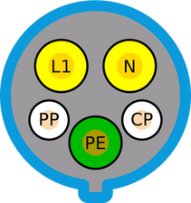 Type 1 (SAE J1772) | 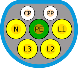 Type 2 (DE, UK) 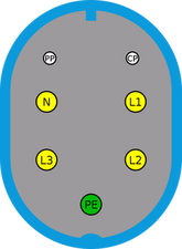 Type 3 (IT, FR; now deprecated) | Type 1 (SAE J1772) | 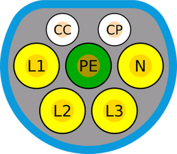 Type 2 (GB/T 20234.2) |
| 3-phase AC | Type 2 (SAE J3068) | - | ||
| DC | 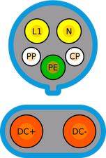 EE (CCS Combo 1) | 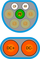 FF (CCS Combo 2) | 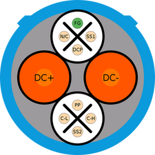 AA (CHAdeMO) | 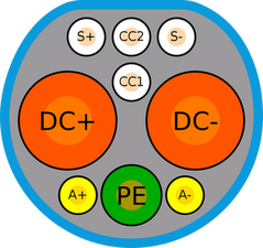 BB (GB/T 20234.3) |
 ChaoJi (planned) | ||||
Historical connectors
In the late 1990s and early 2000s, several electric vehicles (EVs), including the GM EV1, Ford Ranger EV, and Chevrolet S-10 EV, were introduced in the United States. These vehicles favored the use of Level 2 (single-phase AC) Electric Vehicle Supply Equipment (EVSE), as defined by NEC-1999, to maintain an acceptable charging speed. The EVSEs were equipped with either an inductive connector (Magne Charge) or a conductive connector (typically AVCON). GM, Nissan, and Toyota supported the inductive system, while DaimlerChrysler, Ford, and Honda backed the conductive system.
Magne Charge paddles came in two sizes: an older, larger paddle (utilized for the EV1 and S-10 EV) and a newer, smaller paddle (used for the first-generation Toyota RAV4 EV but backward compatible with large-paddle vehicles through an adapter). The larger paddle, introduced in 1994, was necessary for a liquid-cooled vehicle inlet charge port, while the smaller paddle, introduced in 2000, interfaced with an air-cooled inlet instead. SAE J1773, outlining the technical requirements for inductive paddle coupling, was first issued in January 1995, with a revision in November 1999.

The AVCON connector (left) next to its successor, the SAE J1772 connector (right).
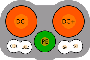
On June 28, 2001, the influential California Air Resources Board adopted the conductive connector as its standard, citing lower costs and greater durability. Consequently, the Magne Charge paddle was discontinued by the following March. Three conductive connectors existed at that time, each named after its manufacturers: Avcon (also known as butt-and-pin, used by Ford, Solectria, and Honda), Yazaki (also known as pin-and-sleeve, on the RAV4 EV), and ODU (used by DaimlerChrysler). The Avcon butt-and-pin connector supported both Level 2 and Level 3 (DC) charging and was initially described in the appendix of the first version (1996) of the SAE J1772 recommended practice. The 2001 version moved the connector description into the body of the practice, establishing it as the de facto standard for the United States. IWC recommended the Avcon butt connector for North America based on environmental and durability testing. In its implementation, the Avcon connector used four contacts for Level 2 (L1, L2, Pilot, Ground) and added five more (three for serial communications and two for DC power) for Level 3 (L1, L2, Pilot, Com1, Com2, Ground, Clean Data ground, DC+, DC−). However, by 2009, J1772 had adopted the round pin-and-sleeve (Yazaki) connector as its standard implementation, rendering the rectangular Avcon butt connector obsolete.

Equipe

0 comentários