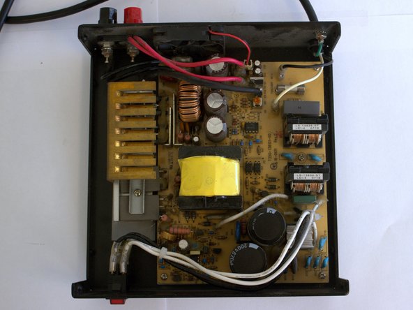
Ir para o conteúdo principal

O que você precisa

Este teardown (desmontagem analítica) não é um guia de reparo. Para reparar seu/sua RadioShack 22-510 Switching Power Supply, use o nosso manual de serviço.

  1. RadioShack 22-510 Switching Power Supply Teardown, Disconnect Supply Power: passo 1, imagem 1 %32 RadioShack 22-510 Switching Power Supply Teardown, Disconnect Supply Power: passo 1, imagem 2 %32
    • Ensure the power supply is unplugged from mains power before continuing. If the device is powered on during disassembly, serious harm or death may occur.

    • The entire power supply can be taken apart with a Phillips screwdriver and adjustable wrench.

  2. RadioShack 22-510 Switching Power Supply Teardown, Remove the Cover: passo 2, imagem 1 %32 RadioShack 22-510 Switching Power Supply Teardown, Remove the Cover: passo 2, imagem 2 %32 RadioShack 22-510 Switching Power Supply Teardown, Remove the Cover: passo 2, imagem 3 %32
    Ferramenta utilizada nesse passo:
    Magnetic Project Mat
    $19.95
    Comprar
    • Removing the eight cover screws on either side of the power supply allows the cover to lift off

    • Screws can be organized using an iFixit Magnetic Project Mat

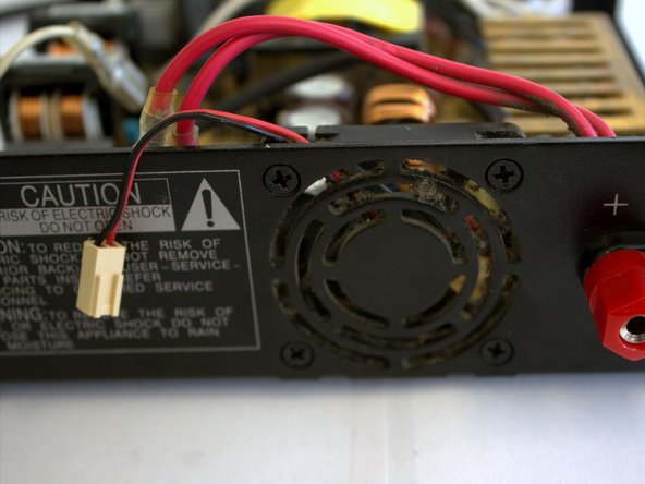
    • A fuse protects the system from overcurrent conditions and the chassis is grounded to protect the user from shorts to the case.

  3. RadioShack 22-510 Switching Power Supply Teardown, Remove Fan: passo 3, imagem 1 %32 RadioShack 22-510 Switching Power Supply Teardown, Remove Fan: passo 3, imagem 2 %32 RadioShack 22-510 Switching Power Supply Teardown, Remove Fan: passo 3, imagem 3 %32
    • The fan connector pulls out by hand. The spade terminal connectors may require coaxing with a pair of pliers.

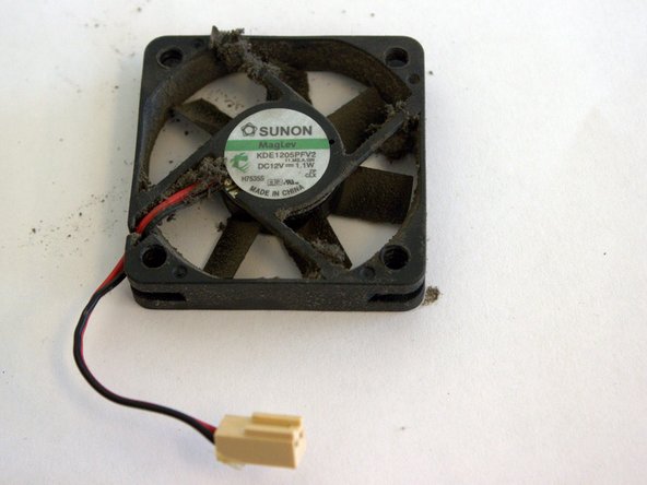
    • The Sunon MagLev KDE1205PFV2 runs at 4300 RPM for a maximum airflow of 13 CFM. A dirty fan might not meet these specifications. Remember to clean your fans!

  4. RadioShack 22-510 Switching Power Supply Teardown, Remove Switch: passo 4, imagem 1 %32 RadioShack 22-510 Switching Power Supply Teardown, Remove Switch: passo 4, imagem 2 %32 RadioShack 22-510 Switching Power Supply Teardown, Remove Switch: passo 4, imagem 3 %32
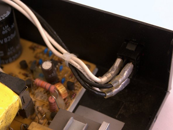
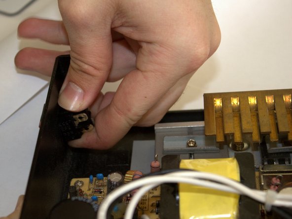
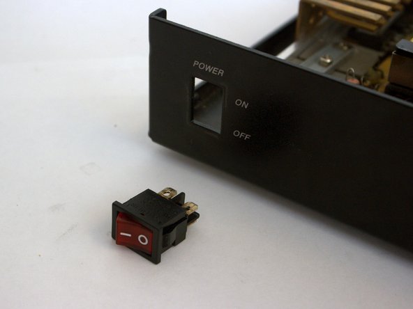
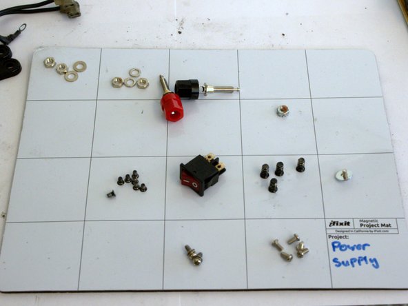
    • The illuminated switch is connected by two sets of black and white AC wires and held in by two locking tabs.

    • The switch is hooked up to the primary side of the circuit. If the switch faults while energized, it has potential to shock the user.

  5. RadioShack 22-510 Switching Power Supply Teardown, Remove Heatsink and Heat Spreader: passo 5, imagem 1 %32 RadioShack 22-510 Switching Power Supply Teardown, Remove Heatsink and Heat Spreader: passo 5, imagem 2 %32
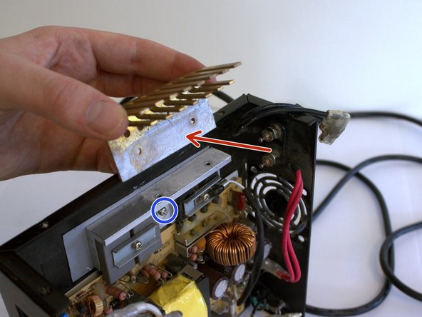
    • Removing the heatsink from the spreader reveals the liberal use of thermal paste. Try not to get it on your hands, it's tough to wash off!

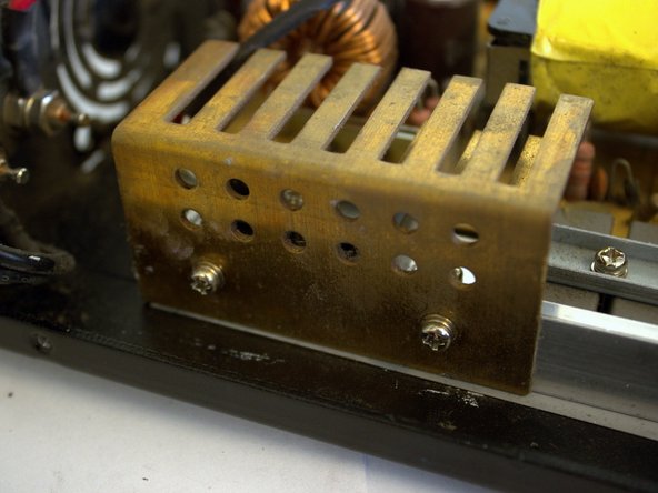
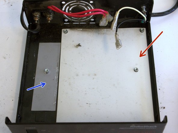
    • The silver heat spreader is screwed to the chassis and must be detached before removing the board.

  6. RadioShack 22-510 Switching Power Supply Teardown, Remove the Board From the Chassis: passo 6, imagem 1 %32 RadioShack 22-510 Switching Power Supply Teardown, Remove the Board From the Chassis: passo 6, imagem 2 %32 RadioShack 22-510 Switching Power Supply Teardown, Remove the Board From the Chassis: passo 6, imagem 3 %32
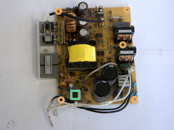
    • The board lifts out of the chassis after removing the five screws holding it down.

    • The capacitors may still be charged, do not touch the terminals! The capacitors can be discharged by shorting the terminals with an insulated screwdriver.

    • The UC3842BN PWM controller handles the switching feedback.

    • The chassis has a sheet of plastic for short circuit prevention under the board.

    • A thermally conductive pad lies under the heatsink assembly for additional cooling capability.

    • Organized parts make reassembly a breeze.

tjlindborg

Membro desde: 08/17/13

111 Reputação

Autoria de 1 guia

0 comentários

Adicione um comentário

Exibir estatísticas:

Últimas 24 horas: 0

Últimos 7 dias: 4

Últimos 30 dias: 9

Duração total: 2,850