Introdução
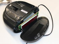
THE RCA RC2012 is a basic alarm clock radio that requires a screwdriver and standard prying tools for tear down.
O que você precisa
-
-
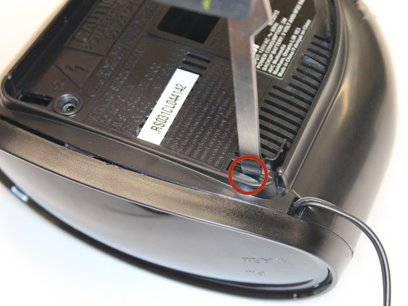
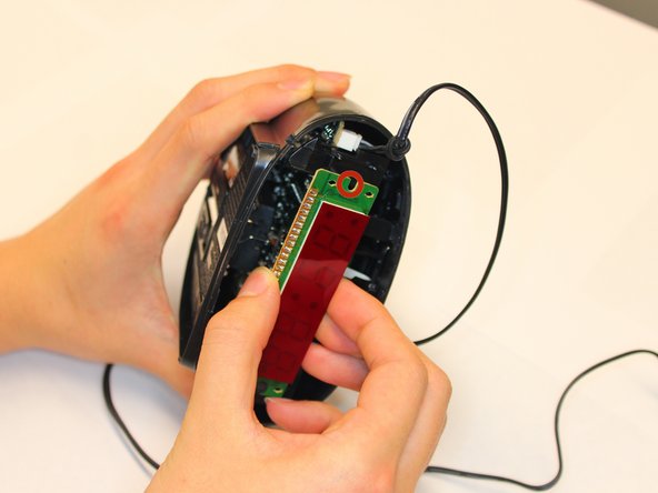
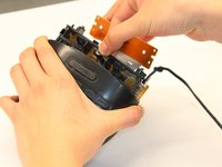
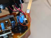
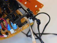
Gently, pry apart the LCD module from the alarm clock. There are two tabs at the edge of the LCD module (marked in red) that hold it in place.
-
Using two fingers work the module back and forth until it separates from the plastic tabs. Be careful of snapping off the plastic tab as this would prevent the LCD module from fitting back in place.
-
-
-
-
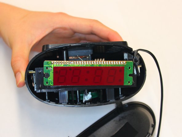
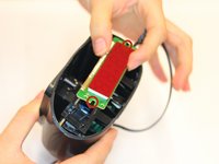
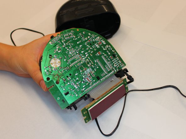
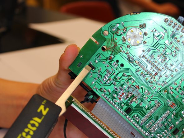
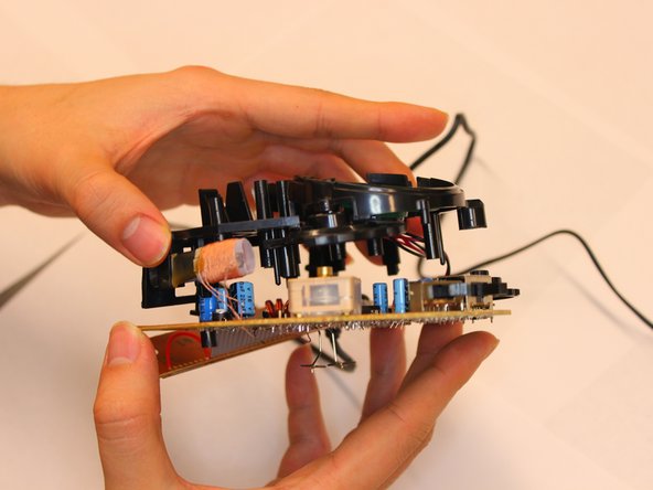
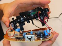
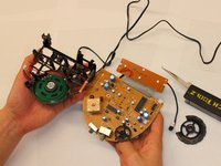
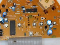
To remove the printer circuit board from the plastic housing, apply firm pressure to both sides of the housing.
-
The PCB is supported by a plastic chassis. Grab the the plastic chassis with one hand while applying pressure to both sides of the alarm clock housing with the other hand.
-
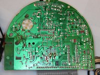
Pull out the PCB from the plastic housing.
-
-
-
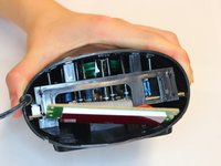
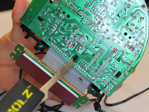
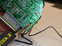
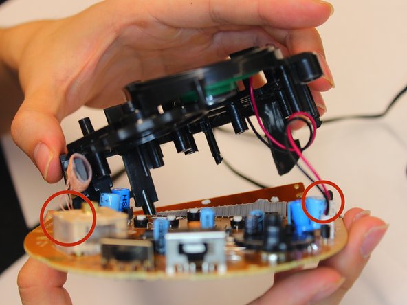
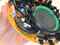
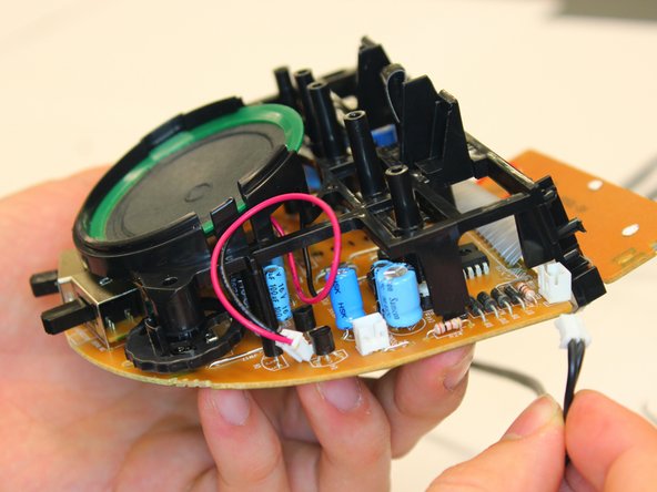
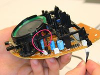
After removing the plastic tabs from under the PCB, carefully lift the plastic chassis away from the PCB.
-
Do not use too much force when pulling apart the chassis from the PCB, there are two sets of two pin connectors and 1 wound up wire for the antenna that remains attached between the chassis and PCB.
-
-
-
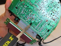
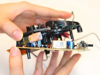
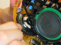
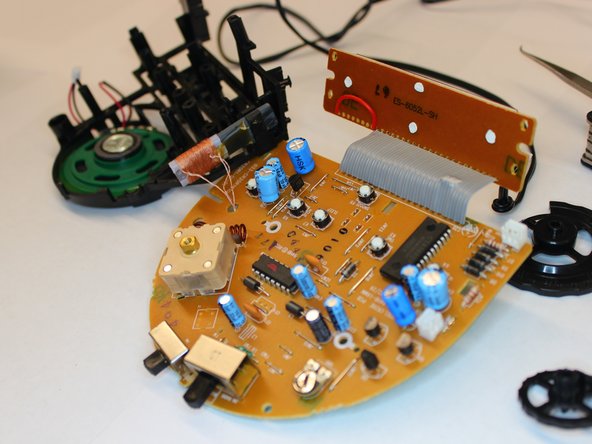
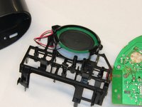
There is a two pin connector that connects the speakers on the chassis to the PCB.
-
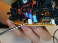
With a small, pointed tool push the two tabs on the two pin connector holding the wire crimps in place. While applying pressure to the two tabs, gently pull the connector wires until the male connector separates from the female counterpart.
-
-
-
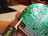
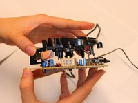
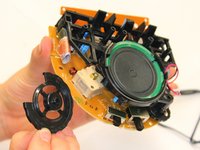
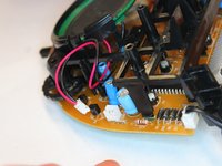
There is a two pin connector on the chassis to the PCB that provides power from the 120VAC adapter.
-
With a small, pointed tool push the two tabs on the two pin connector holding the wire crimps in place. While applying pressure to the two tabs, gently pull the connector wires until the male connector separates from the female counterpart.
-


Equipe

Cal Poly, Team 9-71, Walters Spring 2011 Membro de Cal Poly, Team 9-71, Walters Spring 2011
CPSU-WALTERS-S11S9G71
4 Membros
Autoria de 9 guias