Introdução
How to take apart the M6013 Capacitor Meter
O que você precisa
-
-
-
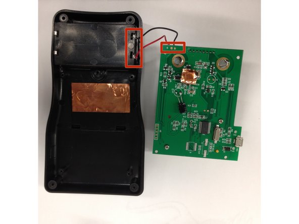
Remove circled screws
-
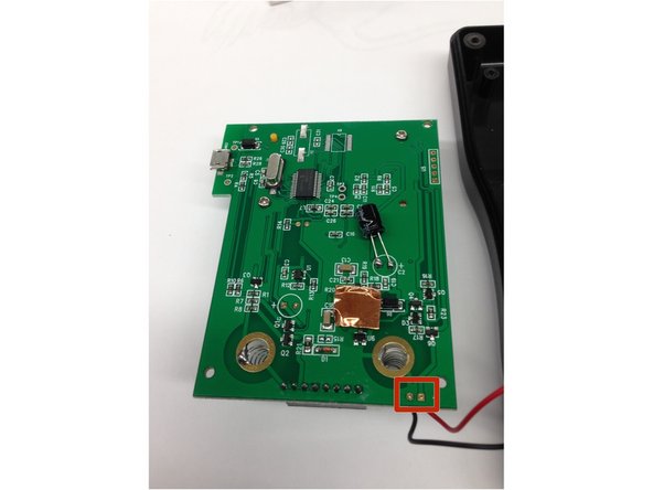
Unsolder the square locations either on the circuit board or the case to fully remove the circuit board
-


Equipe

Cal Poly, Team 16-56, Forte Fall 2012 Membro de Cal Poly, Team 16-56, Forte Fall 2012
CPSU-FORTE-F12S16G56
Membros da 5
Autoria de 13 guias