Esta versão pode conter edições incorretas. Mude para o último instantâneo verificado.
O que você precisa
-
-
Encha uma panela ou frigideira com água suficiente para submergir completamente um iOpener.
-
Aqueça a água até ferver. Desligue o fogo.
-
Coloque um iOpener na água quente por 2 a 3 minutos. Certifique-se de que o iOpener esteja totalmente submerso na água.
-
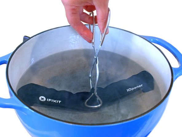
Use um pegador para retirar o iOpener aquecido da água quente.
-
Seque bem o iOpener com uma toalha.
-
Sua bolsa térmica iOpener está pronta para o uso! Se precisar reaquecer o iOpener, aqueça a água até ferver, desligue o fogo e coloque o iOpener na água por 2 a 3 minutos.
-
-
Este passo não foi traduzido. Ajude a traduzi-lo
-
Lay the iOpener over the plastic tab to loosen the adhesive. Let the bag sit on the device for approximately 90 seconds before attempting to open the panel.
-
-
Este passo não foi traduzido. Ajude a traduzi-lo
-
Use a plastic opening tool to pull the rear plastic cover away from the device until there is enough room to insert a spudger.
-
Insert a spudger under the cover, then pry it up and away from the device.
-
Remove the rear plastic cover from the iPod.
-
-
Este passo não foi traduzido. Ajude a traduzi-lo
-
Remove the single 1.4 mm Phillips #000 screw from the black plastic spacer.
-
-
Este passo não foi traduzido. Ajude a traduzi-lo
-
Use a plastic opening tool to remove the black plastic spacer from the Nano.
-
-
Este passo não foi traduzido. Ajude a traduzi-lo
-
Remove the two 2 mm Phillips #000 screws from the bottom of the case.
-
-
Este passo não foi traduzido. Ajude a traduzi-lo
-
Insert a plastic opening tool into the seam between the white plastic front panel and the rear case.
-
Slide the opening tool along the edge of the front panel to free it from clips and adhesive.
-
-
-
Este passo não foi traduzido. Ajude a traduzi-lo
-
Use a spudger to press the midframe screw tab up and out of the rear case.
-
-
Este passo não foi traduzido. Ajude a traduzi-lo
-
Use a metal spudger to carefully pry near the Lightning connector and under all parts of the front panel assembly: the front glass/digitizer, the LCD display and the metal midframe.
-
-
Este passo não foi traduzido. Ajude a traduzi-lo
-
Continue prying along the edges under the front panel assembly, releasing the clips and adhesive along the sides of the device.
-
-
Este passo não foi traduzido. Ajude a traduzi-lo
-
Pull the front panel assembly slightly down and partially out of the device.
-
-
Este passo não foi traduzido. Ajude a traduzi-lo
-
Use a spudger to release the digitizer cable and display data cable connectors.
-
-
Este passo não foi traduzido. Ajude a traduzi-lo
-
Gently unfold the two halves of the device to access the internal components.
-
-
Este passo não foi traduzido. Ajude a traduzi-lo
-
Pull up on the battery pull tab to free the battery from its adhesive.
-
-
Este passo não foi traduzido. Ajude a traduzi-lo
-
Completely separate the front panel assembly from the rest of the device.
-
-
Este passo não foi traduzido. Ajude a traduzi-lo
-
Remove the two 1.4 mm Phillips #000 screws from the sleep/power button bracket.
-
-
Este passo não foi traduzido. Ajude a traduzi-lo
-
Remove the sleep/power button bracket from the rear case.
-
-
Este passo não foi traduzido. Ajude a traduzi-lo
-
Insert a plastic opening tool under the sleep/power button, and gently pry upwards to free it from its adhesive.
-
Slide the plastic opening tool along the underside of the sleep/power button ribbon cable.
-
-
Este passo não foi traduzido. Ajude a traduzi-lo
-
Peel back and remove any tape covering the volume control button assembly.
-
-
Este passo não foi traduzido. Ajude a traduzi-lo
-
Remove the three 1.4 mm Phillips #000 screws securing the volume control button assembly to the rear case.
-
-
Este passo não foi traduzido. Ajude a traduzi-lo
-
Use the pointed end of a spudger to pry the volume control button assembly away from the edge of the case.
-
-
Este passo não foi traduzido. Ajude a traduzi-lo
-
Remove the single 2.8 mm Phillips #000 screw from the headphone jack.
-
Remove the 4 Phillips #000 screws from the lightning connector and logic board.
-
-
Este passo não foi traduzido. Ajude a traduzi-lo
-
Use a spudger to pry the headphone jack off of the adhesive holding it to the rear case.
-
-
Este passo não foi traduzido. Ajude a traduzi-lo
-
Use the flat end of a spudger to push the logic board away from the edges of the rear case to free the Lightning connector.
-
Once the Lightning connector has been loosened, push gently between it and the case to further free it.
-
-
Este passo não foi traduzido. Ajude a traduzi-lo
-
Gently pull the logic board assembly out of the rear case.
-


Cancelar: não concluí este guia.
19 outras pessoas executaram este guia.


12 comentários
Fixing the headphone jack is super hard. I've been working on mine for a few months. And Basically I ordered the part on ebay (headphone jack, the power button is attached) and I pulled it apart, opened the ipod and swapped everything out (pay close attention to where pieces go cause there's no YouTube videos on how to do it yet) but there is a small piece attached to the ribbon cable near the headphone jack (it's square shaped, with looks like little grid thing, not sure the name) and it has to be perfectly lined up and contacts have to be touching for the power button, volume controls, an headphone jack to work. And that's where I'm stuck cause you can't use adhesive or it will block the contact points. So if you can find someone to replace your ipod parts it will be much easier.